
Beam forming technology invading consumer applications
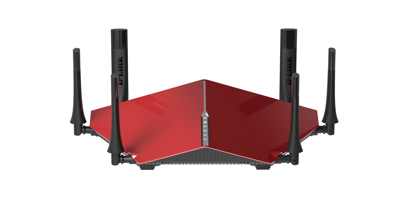

Figure 1 Dell’s 802.11ac WiFi router with 8 antennas for beamforming
Abstract: Traditional antennas used in WiFi routers were of the omnidirectional nature, meaning that they radiated in all directions equally and also received power from all directions equally. Whereas, most of the times, a user connected to WiFi router will be stationary and only a certain amount of power radiated by the router will be actually utilized. Considering this fact that most of the power is wasted, the idea of beam forming concept was born which tries to form a beam of radiation directed at the location of the user. Thus, instead of radiating power in all directions, the radio waves will now be directed only towards the user providing him with much higher signal strength and also better data rate (speed). Modern beam forming techniques have achieved the ability to form not just single beam but multiple beams in various directions. Many WiFi routers have ability to track the location of the user in the signal range and make the radio beam follow the user wherever he is moving.
Beam forming in WiFi 802.11ac standard
Beam forming was first taken as part of the WiFi standard when the 802.11n version of WiFi was released some years ago. At that time IEEE (the institution which standardizes many electronic protocols and technologies) did not standardize how this beam forming technology has to be implemented in our WiFi routers. Anyone can implement beam forming the way he wishes. There are always more than one ways to do something. For example, Cisco might implement a different protocol in the beam forming implementation in their routers whereas Alcatel might make wireless network cards that implement the same technology in a different way. The Alcatel and Cisco products will become incompatible with each other and be of no use. Thus, 802.11n standard never had any products that utilized beam forming technology. IEEE standardized this technology in the recent 802.11ac standard and only then have products come out in the market that are able to reach multi gigabit data transfer speeds achieved due to the highly directional beam forming capabilities of consumer grade routers.
Any router that has more than 1 antenna is capable of forming beams in various directions. I am sure you might have seen WiFi routers that have 2 or 3 or even 8 antennas. The purpose of these antennas is to create highly directional beams. The more the number of antennas, the higher is the ability to track user movements across the range.
Figure 1 Dell’s 802.11ac WiFi router with 8 antennas for beamforming
How beams are formed
Each antenna on a WiFi router is omnidirectional. That is, it radiates power in all directions. We must also keep in mind that the same antenna is also used for receiving signals from the user device. Thus, each antenna does the job of transmit and receive at same time. The following diagram will give a better understanding of the word “omnidirectional”.

Figure 2 Omnidirectional antenna radiation pattern
To our importance is the “Azimuth plane radiation pattern” which shows that the antenna radiates equal power in the horizontal plane (X-Y axis). There exists no truly omnidirectional antenna in this world at this point in time that can radiate equal power in all directions. Which becomes clear when we see the second radiation pattern in the “Elevation plane”, that is the vertical plane (Z-axis). Even if the antenna radiates and receives power equally in horizontal plane, it has a very different radiation characteristic in the vertical direction. Even so, we call this an omnidirectional antenna.
A simplified list of steps to understand beam forming with 2 antennas
- Now consider that there are 2 such omnidirectional antennas kept side by side in a line.
- Distance between the two antennas is fixed and stored in the WiFi router’s firmware memory.
- Time taken for the radio wave from antenna A to B is and B to A is calculated and also stored in firmware.
- User’s location in the room is calculated dynamically by monitoring the direction from which the signals are being received from the user’s device. Using this location, the angle is calculated to form the beam in direction of user.
- Once the angle is known, the transmit signal in one of the antennas is delayed by a certain amount of time (in technical terms it is said “phase shifted by certain degrees angle”).
- In the figure 2, the user is on the right hand side of the antenna array. Thus, antenna B is closer to the user than the antenna A. Wave emitted by the antenna B will reach the user first and then the wave from antenna A will reach after a certain delay.
- If the wave from antenna B is delayed by time ‘t’, then both waves from antenna A and B will reach at the same time in the location of user. Here, time ‘t’ is the time taken by the wave to travel from antenna A to the user such that both waves from A and B reach at same time
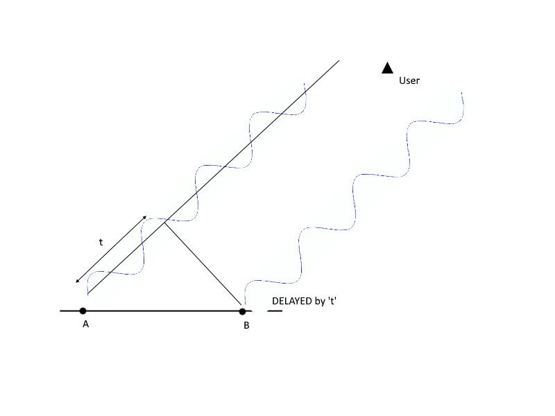
Figure 3 Concept of Phase delay
This was a much simpler example to understand the concept of beam forming where only two antennas were involved and only one user was present. In practical situations, there could be two users sitting in different locations and beams need to be formed in both the directions. At that time, a much more complex algorithms are implemented to continuously monitor the received signal strength and track the user’s location for creating a directive beam.
The beam formation is just one of the parts of the entire WiFi communication system and it has been proving itself to be very successful in providing multi gigabit wireless links to users.
Simplified protocol model
The WiFi router and the user device initially exchange a series of messages which help in measuring the signal quality being received by the user and the signal quality received by the router. This process is called channel calibration.

Figure 4 No steering matrix applied, no phase change
- The channel calibration happens with the help of Null Data Packet (NDP). Router transmits blank packets of data and it is received by the users.
- User’s device will automatically acknowledge the receipt of the packet. With the acknowledgement packet, router will know come to know the identity of all the users connected.
- The acknowledgement of the NDP from the user will help router calculate the quality of the wireless communication channel and also help in calculating the transmission signal power.
- In addition to that, there is something called as “OFDM training fields” in the NDP. User’s device will use these training fields in the packet to calculate a “steering” matrix which will be sent back to the router.
- Initially, when the beam is not formed, router transmits signals without applying any phase shift to the antenna array. Thus, we get an omnidirectional response from the router as we saw earlier.
- When phase shifting is applied to the antennas, like we saw earlier, we get an effect of beam formation. To determine which antenna must apply what amount of phase shift is determined by this “steering matrix”. Once router receives this steering matrix, it is applied to the antennas and beam formation can happen.
The entire algorithm is continuously running to monitor the location of the user and the user’s device continuously calculates a steering matrix and sends it back to router. Thus, we have an effect where it seems like the router is able to see you wherever you go in its range of operation.
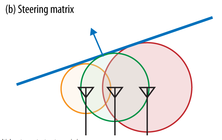
Figure 5 Steering matrix applied, beam formed.
Beam forming in audio applications
The beam forming concept is no longer limited to WiFi routers, in fact XBOX Kinect gaming console has implemented a similar beam forming concept in audio application to track the position of the user in the room and pick up voice commands while rejecting background noise. Instead of antennas, we have microphones working inside the Kinect. It is also interesting to know that it is beam forming technique that creates the virtual surround sound effect in our home theatre setups involving a “sound bar”.
A recent research publication from [2] Philips audio solutions showed that their beam forming implementation for audio systems was able to direct the sound to the user watching a movie, and a person sitting a few inches away from him was unable to hear any sound. Such is the power of beam forming technology. In another scenario, Philips’ experiment showed that the beam forming technology can be useful for partially dead people who need higher volume than everyone else. Using this technology, a higher volume of sound can be transmitted towards a deaf individual while a lower volume for everyone else in the room.
References:
[1]. Matthew S. Gast. “802.11ac: A Survival Guide”. E-Book. 2013. Web.
[2]. Wener de Burjin. “Making All the Right Noises: Shaping sound with Audio Beamforming”. Philips Research. Web.


Voice of the people