Transmitting SSB audio with LimeSDR Mini

There are so many new RF devices coming out these days which has pushed the envelope the technology where a common person can access it. In one of the previous posts, I demonstrated how LimeSDR mini can be used like a RF source. This time, we will be looking at generating SSB (Single Side band) Amplitude modulation. SSB Transmission with LimeSDR Mini can be a useful thing for those trying to get their setup ready for QO-100 satellite. The QO-100 satellite up-link has a frequency in the 2.4GHz band. Most of our Ham radio equipment operates in the HF and V/UHF bands. A very few transceivers generate SSB in these bands. For someone with a transmit capable SDR can follow this method to generate SSB.
Setting up
We will be making use of LimeSDR Mini and GNU Radio to generate SSB modulation. By the end of the article you should be able to generate SSB at any frequency you desire. While dealing with SDRs, we mostly deal with data in the base band region where frequencies are low. LimeSDR has an up-converting IQ modulator which works to our advantage. Additionally, the transmit side PLL in LimeSDR generates complex outputs. In other words, it generates \(cos(2\pi ft)\) and \(sin(2\pi ft)\) to drive the IQ mixer. As a result of the IQ mixer, we are able to obtain single side band output with good side band image rejection.
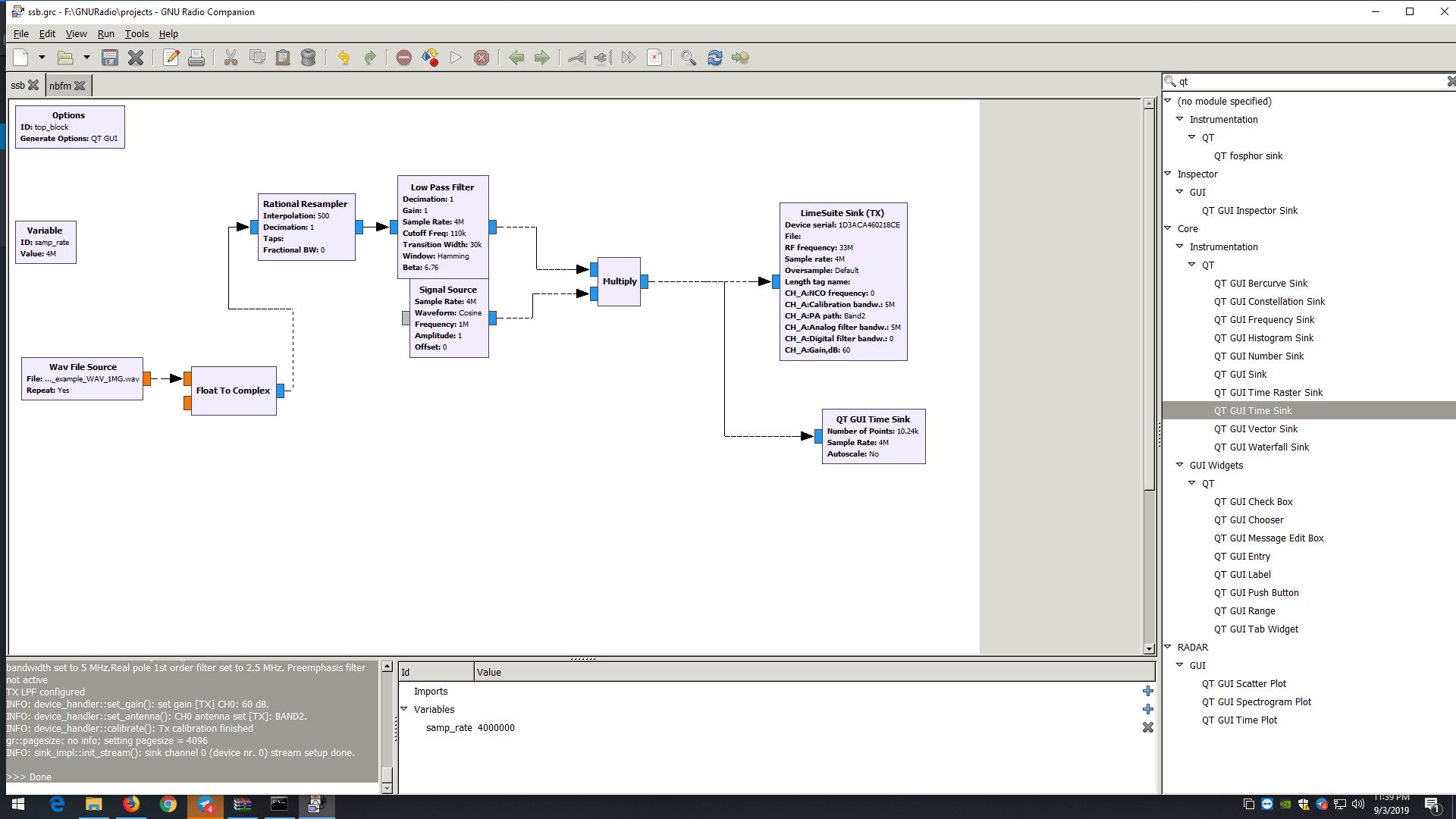
First, we run the GNU radio companion and place the audio source block. We will be using a short audio clip in .wav format and re-sampling it to match the sample rate at which we are running LimeSDR. The wav file that we are using has a sample rate of \(8kHz\) and we are feeding the LimeSDR at \(4MSPS\). Therefore, the data needs to be re-sampled by a scale of 500.

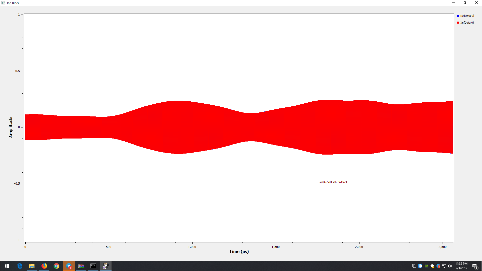
The rational re-sampler does exactly this, up-samples it in this case. Further, we want our single side band output to be slightly away from the carrier. For this reason, we are mixing the audio data with a \(1MHz\) carrier. The result of this process gives us an amplitude modulated complex waveform.

The LimeSDR TX PLL is set to \(2401MHz\). I am using this frequency so that I can uplink to QO-100 narrowband transponder. As mentioned earlier, the TX PLL of LimeSDR Mini generates complex waveform which then drives the IQ mixer. It is common knowledge that IQ mixers are known as “Image Reject” mixers because of their ability to suppress the side band image.
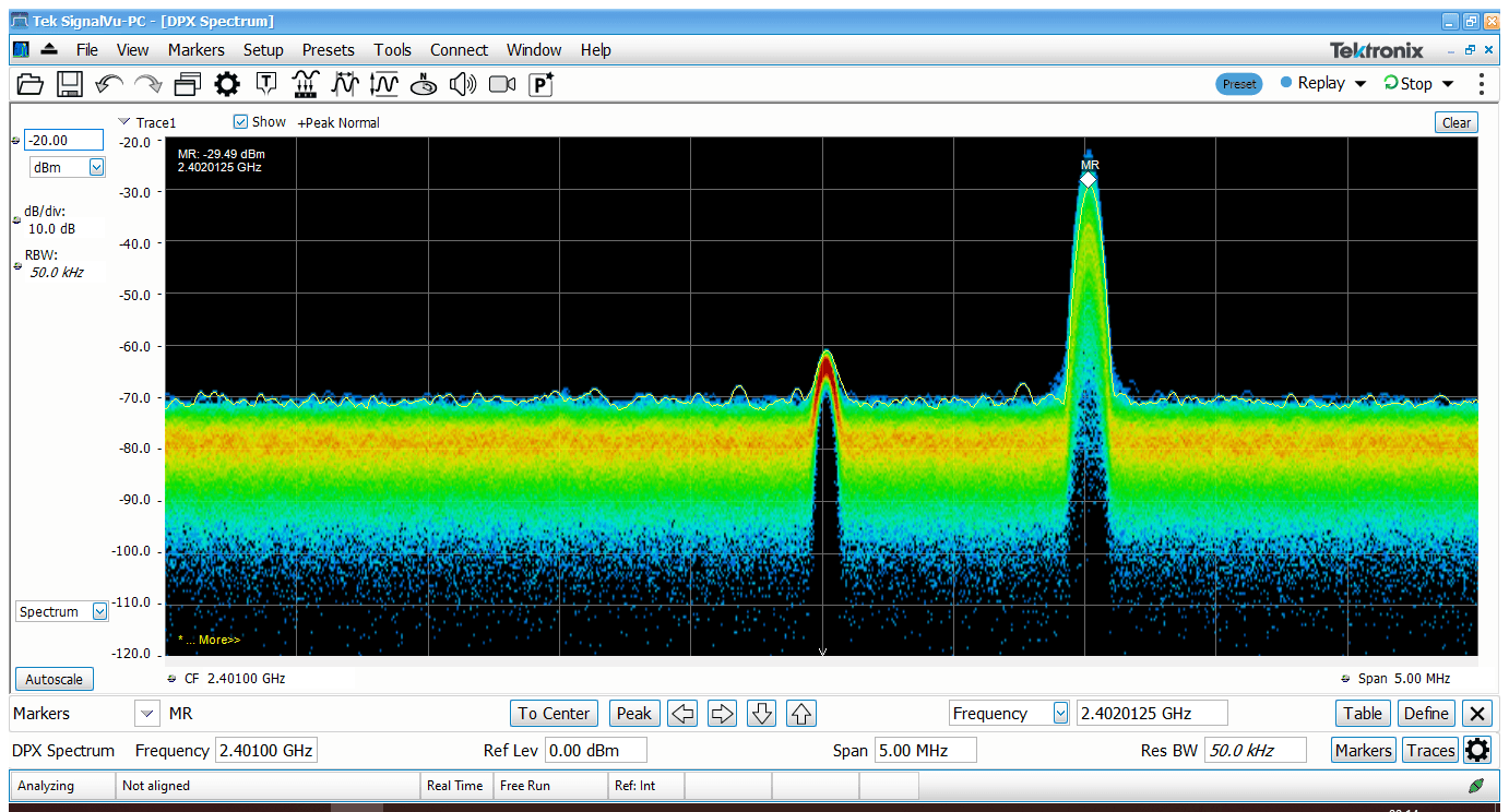
You must have guessed already. The output of the LimeSDR is going to be a single side band containing our audio. Mathematically, the mixing process should result in two side bands \(1MHz\) apart from the carrier. Precisely, the lower side band must occur at \(2401-1 = 2400MHz\) and the upper side band must occur at \(2401+1 = 2402MHz\) Let us confirm this by looking at the spectrum analyzer output. Fortunately, I have access to Tektronix RSA306B spectrum analyzer. For those who don’t know, RSA306B is a 6GHz real time spectrum analyzer with \(40MHz\) real time bandwidth.
Coming back to the point, let us observe the SSB spectrum on RSA306B.

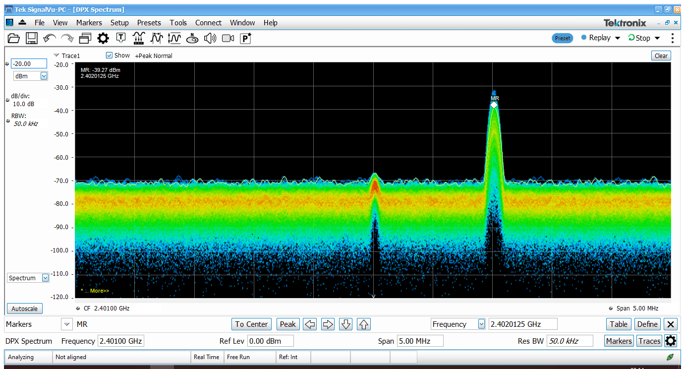
I have set the center frequency of the spectrum analyzer to \(2401MHz\). We can observe the \(2401MHz\) carrier frequency and the upper side band occurring at \(2402MHz\). A very faint peak also appears at \(2400MHz\) which is the residue of the lower side band due to the circuit non-linearities. We can further reduce the lower side band or rather, the unwanted side band by reducing the \(TX Gain\) parameter in the LimeTX block. Let us again observe the spectrum to see if we have made any improvements.

Looking at the spectrum, the residues of the lower side band seem to have vanished in the noise floor. And thus, we have generated single side band output with the LimeSDR mini and possibly learnt a couple of new things as well.
Let me know in the comments below about what you plan to use this for.


Informative article, especially for a beginner like me.
That’s remarkable Salil!