Generating PWM on Tiva C connected launchpad (TM4C1294)
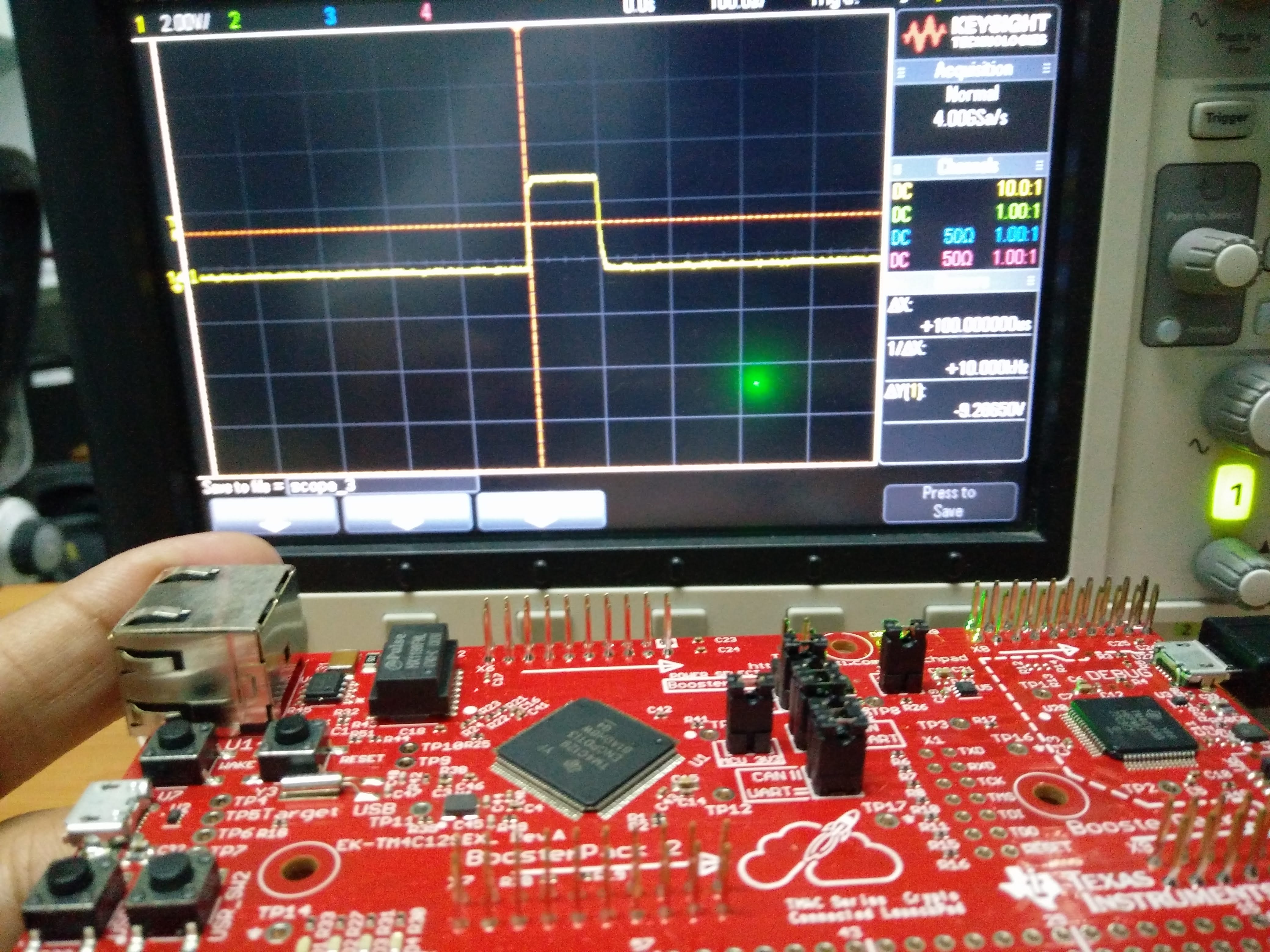
Texas Instrument’s Tiva C connected launchpad is a really powerful Cortex M4 microcontroller board. The possibilities with this chip are endless. In this post, we will be generating PWM output on one of the GPIO pins of TM4C1294 microcontroller. A simple PWM output can be of great use in many applications. Few of the common applications include motor control, LED brightness control, switching solid state relays and so on. On the other hand, I have something else in my mind. I plan on using this PWM output to toggle Minicircuits RF SP2T switch for generating pulsed RF. We will that discussion for a second part of this article. Meanwhile, we will have a quick look on generating PWM with the Tiva microcontroller.
Let us define a few things before we begin.
|
1 2 3 |
Pulse Width: 100ns Frequency: 10kHz System Clock: 120MHz |
We will use Port G pin 1 on the microcontroller as our PWM output pin.
Let’s begin
Let us begin by enabling a few things.
|
1 2 3 4 5 6 7 |
sysclock = SysCtlClockFreqSet((SYSCTL_XTAL_25MHZ | SYSCTL_OSC_MAIN | SYSCTL_USE_PLL | SYSCTL_CFG_VCO_480), CPU_FREQ); SysCtlPWMClockSet(SYSCTL_PWMDIV_1); // Enable clock to PWM module SysCtlPeripheralEnable(SYSCTL_PERIPH_PWM0); // Use PWM module 0 SysCtlPeripheralEnable(SYSCTL_PERIPH_GPIOG);// Enable Port G |
We have to use the PWM module 0 since it is connected to Port G pin 1 as defined in the data sheet.
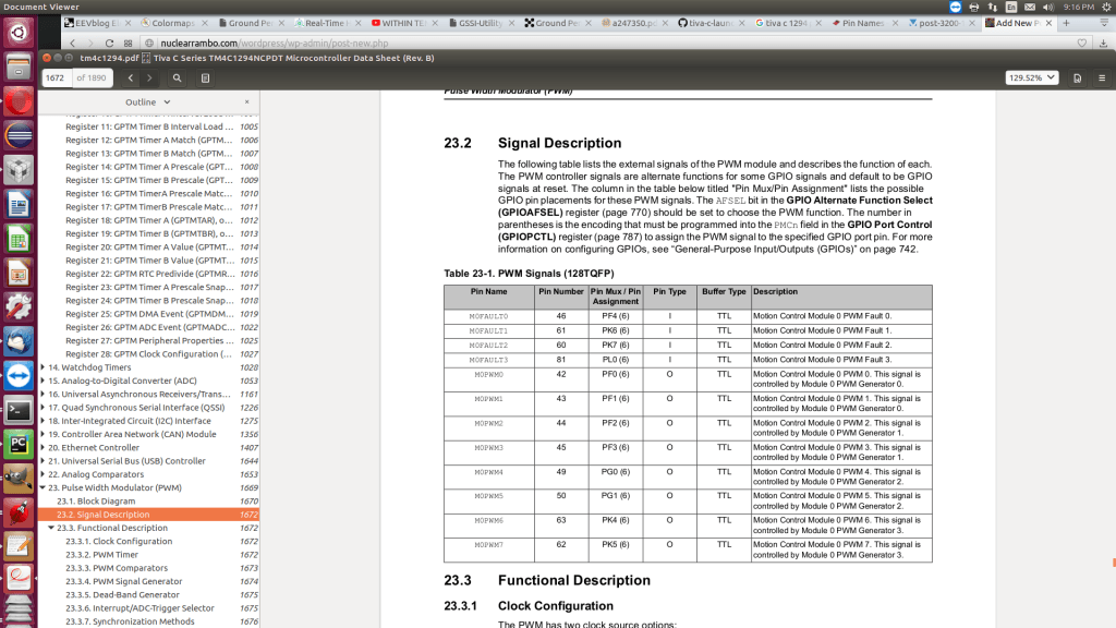
Moving ahead, we will now enable the alternate function of the GPIOG Pin 1, that is, PWM-channel-5. Furthermore, we will configure the PWM module to work in UP-DOWN mode, set the frequency and duty cycle. Finally, we shall enable the output and observe waveform on an oscilloscope.
|
1 2 3 4 5 6 |
GPIOPinConfigure(GPIO_PG1_M0PWM5); // Enable alternate function of PG1 PWMGenConfigure(PWM0_BASE, PWM_GEN_2, PWM_GEN_MODE_UP_DOWN | PWM_GEN_MODE_DB_NO_SYNC); PWMGenPeriodSet(PWM0_BASE, PWM_GEN_2, pwm_word); // Set PWM frequency PWMPulseWidthSet(PWM0_BASE, PWM_OUT_5, PWMGenPeriodGet(PWM0_BASE, PWM_GEN_2)/1000); // Set Duty cycle PWMOutputState(PWM0_BASE, PWM_OUT_5_BIT, true); // Enable PWM output channel 5 PWMGenEnable(PWM0_BASE, PWM_GEN_2); // Enable PWM module |
You may have noticed the variable “pwm_word” and wondered what that is. According to data sheet, the frequency is calculated according to the following equation:
|
1 |
pwm_word = (1/PWM_Frequency) * CPU Frequency |
Finally, we end the configuration with a…
|
1 |
while(1); |
Now, we should see the desired PWM output on the screen.
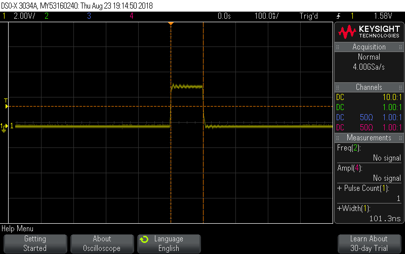
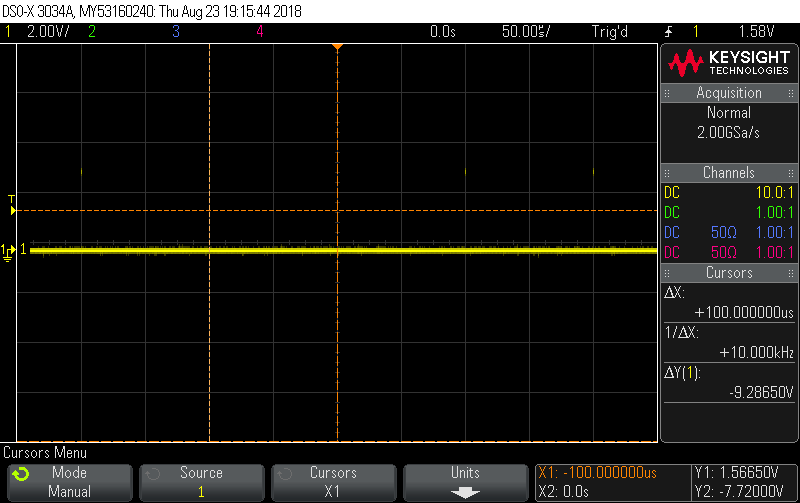
In the next article we will look at how this waveforms helps in producing a pulsed RF waveform. I am sure you will find that one interesting as well!
You can find the complete code below.
|
1 2 3 4 5 6 7 8 9 10 11 12 13 14 15 16 17 18 19 20 21 22 23 24 25 26 27 28 29 30 31 32 33 34 35 36 37 38 39 40 |
#include <stdint.h> #include <stdbool.h> #include "inc/hw_ints.h" #include "inc/hw_memmap.h" #include "inc/hw_types.h" #include "driverlib/debug.h" #include "driverlib/gpio.h" #include "driverlib/pin_map.h" #include "driverlib/sysctl.h" #include "driverlib/pwm.h" uint32_t sysclock; void main() { float PWM_FREQ; float CPU_FREQ; float pwm_word; PWM_FREQ = 10000; //10khz CPU_FREQ = 120000000; pwm_word = (1/PWM_FREQ)*CPU_FREQ; sysclock = SysCtlClockFreqSet((SYSCTL_XTAL_25MHZ | SYSCTL_OSC_MAIN | SYSCTL_USE_PLL | SYSCTL_CFG_VCO_480), CPU_FREQ); SysCtlPWMClockSet(SYSCTL_PWMDIV_1); SysCtlPeripheralEnable(SYSCTL_PERIPH_PWM0); SysCtlPeripheralEnable(SYSCTL_PERIPH_GPIOG); GPIOPinTypePWM(GPIO_PORTG_BASE, GPIO_PIN_1); GPIOPinConfigure(GPIO_PG1_M0PWM5); PWMGenConfigure(PWM0_BASE, PWM_GEN_2, PWM_GEN_MODE_UP_DOWN | PWM_GEN_MODE_DB_NO_SYNC); PWMGenPeriodSet(PWM0_BASE, PWM_GEN_2, pwm_word); PWMPulseWidthSet(PWM0_BASE, PWM_OUT_5, PWMGenPeriodGet(PWM0_BASE, PWM_GEN_2)/1000); PWMOutputState(PWM0_BASE, PWM_OUT_5_BIT, true); PWMGenEnable(PWM0_BASE, PWM_GEN_2); while(1); } |


Complex one….but enjoyed reading programming…interesting PWM