
A simple voice detector circuit
Voice detector can find it’s use in voice-activated circuits. For example, triggering a transmitter or enabling a speech processor and so on. At the end of this blog post, we will look at one such application. A voice detector is a circuit which will either give a logic 0 for the presence of sound and logic 1 for an absence of sound or vice versa. Without further wasting more words, let us understand the signal we are dealing with.
Nature of the signal
Voice, if converted into electrical signal, will show the voltage that alternates above and below zero volt line. In other words, it is an AC signal.
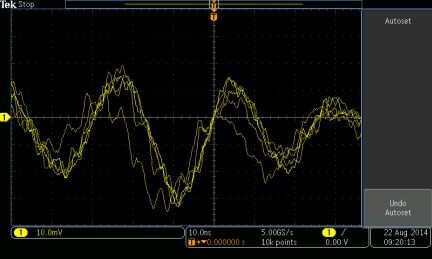
Using a simple peak detector circuit will convert the AC nature of the signal into a DC signal. The DC level will be directly proportional to the amplitude of the voice. We also need to take care of the bandwidth of the voice detector because a higher bandwidth will result in a higher noise floor which will cause false triggering. A low pass filter designed for 5kHz should be more than sufficient.
The schematic
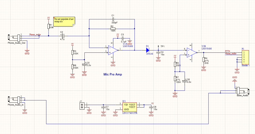
Now, a voice detector could sense voice through a microphone or a direct input. A microphone biasing resistor R1 of value between 4.7K to 10K needs to be connected or disconnected depending on what kind of input you are expecting. You could even leave the R1 in the circuit even if you do not want to feed audio through a microphone. That’s because most audio output ports are AC coupled.
Let’s understand the voice detector circuit
Audio comes in through the jack, get AC coupled through the capacitor C2 into the amplifier U1A which could be an LM358 or a TL072 (or something else). Resistor R2 and capacitor C2 combined give a low pass filter response with a corner frequency of ~5kHz.
The amplified audio now passes through diode D1 which again could be a 1N4XXX, SS3X, 1N58XX and so on. I have tried with 1N4148, SS34 and 1N5819 and the circuit works fantastic. Resistors R3 and R6 offset the output by Vcc/2. Considering our supply voltage to be 5V, the offset stands at 2.5V. We will treat this voltage as the zero reference. In other words, lack of audio will result in 2.5V output whereas, the presence of sound should result in a voltage higher than 2.5V. A decision circuit will give us a definitive answer whether audio is present at the input or not. This decision circuit happens to be a simple comparator. The Opamp LM358 happen to be dual opamp. Using the first opamp for amplification leaves us with one more opamp to be used as a comparator.
I set the comparator threshold to 3.0V with the help a voltage divider formed with two resistors R5 and R7. Since I am following negative logic, the comparator will output logic 1 in the absence of voice and a logic 0 otherwise. The Opamp LM358 not being a rail-rail opamp, the logic 1 voltage will never touch 5V (Vcc). It will always be in the vicinity of Vcc-1.2V. So, a high voltage of 3.8V was observed at the final output.
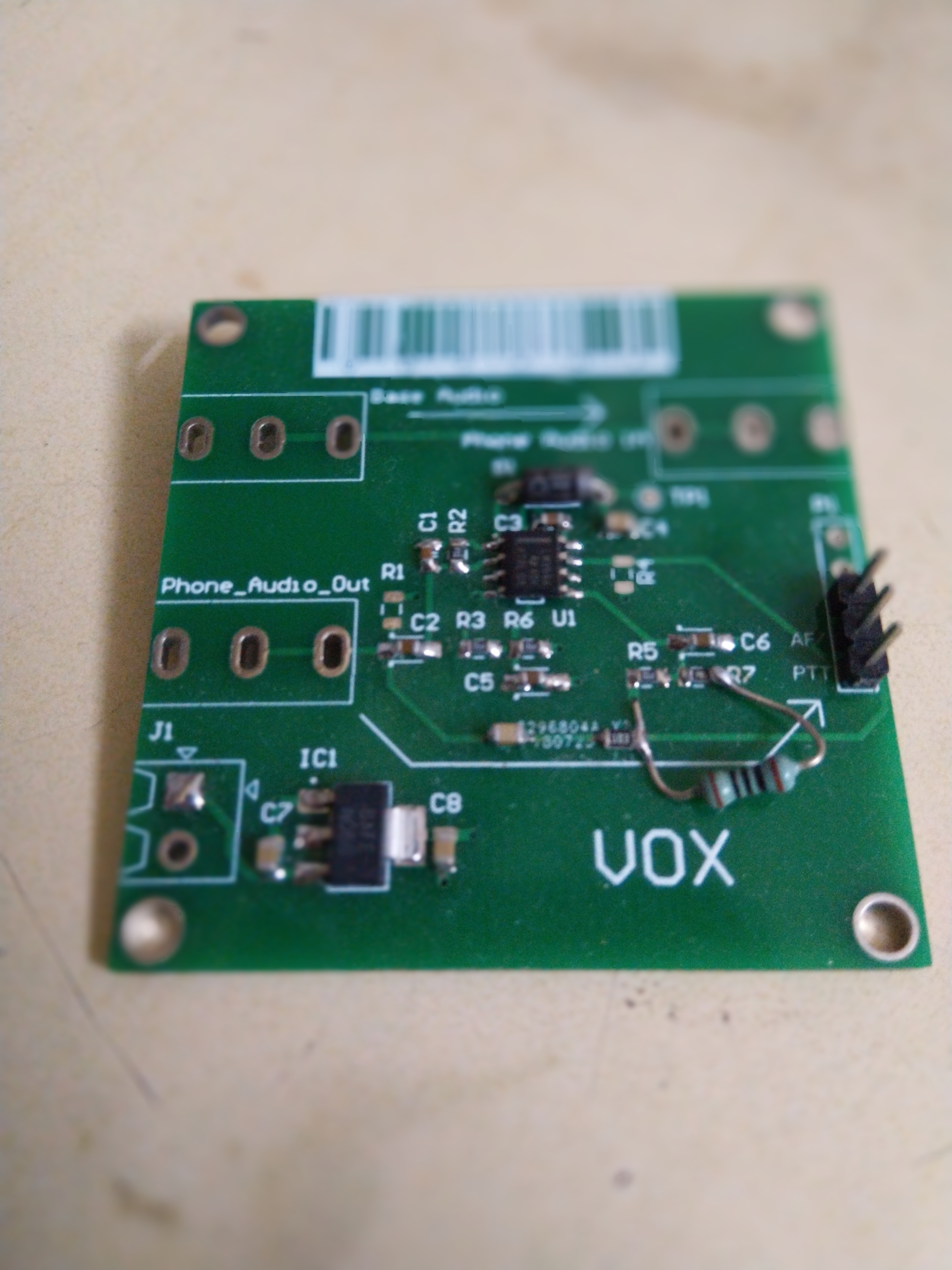
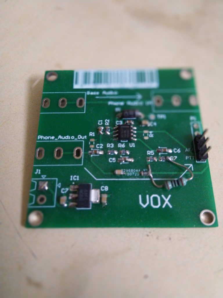
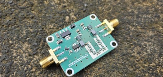
The PCB was quite simple to make. I got it fabricated from JLCPCB for $2 + shipping and the results were stunning. Check out the photograph below.
Want the gerber files or the schematic? Comment below!
You can also get it fabricated from our sponsor Seeed Fusion where you can quickly get your PCB assembled as well.


Good stuff Salil…..
i need pspice orcad software