
Capturing video with Petalinux – Part 1 – The hardware design
In one of the previous articles, I showed you how you could build a basic design on Zynq SoC and boot Petalinux over it. This article would be an extension to the previous one. Our goal for this time would be capturing video frames and saving them as raw files. Sounds simple when you have the entire Linux already set up for you. When it comes to building one from scratch, it won’t be very easy. Especially, when you are doing it all for the first time. It took me several week’s worth of effort that included reading documentation, forums posts and trying out various things. For some, the amount of struggle might be lower than what I had to endure throughout the process. Nevertheless, it was an interesting project that I would be presenting here in multiple parts. Well, multiple parts, because I am still not done yet.
The hardware design
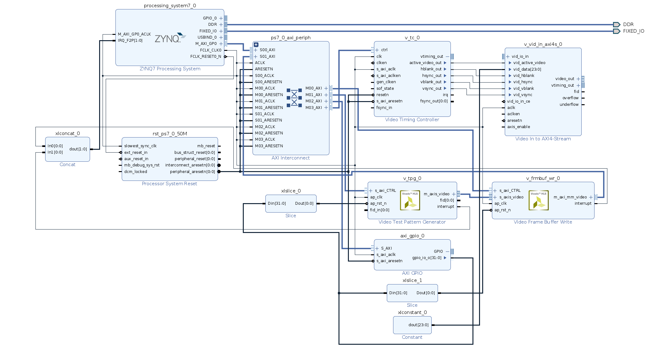
The hardware design consists of the Zynq Processing System block configured to output an additional clock of 144.9 MHz to support full HD resolution. You could work with lower clock speeds but that might reduce your frame rate as you go for higher resolution frames.
Next, we add the Video test pattern generator (TPG) and video frame buffer writer blocks. If you are struggling with this part, I highly recommend you read my previous article and then come back here.
You will also need to add the video timing controller (VTC) block. As such, this block isn’t very useful if you aren’t pushing your video out through any display interface. The TPG Linux driver looks for the timing controller and fails if it isn’t in the design. This reason forces us to include the VTC block in spite of not pushing the video out over any interface.
Also, add the AXI GPIO block in your design and this is required by the Video4Linux2 (V4L2) API. This AXI GPIO block will connect to the reset pins of the test pattern generator and the frame buffer writer that we have in the system. When we finally have our system ready for use, we would be using V4L2 for configuring our video pipeline. It’s during the configuration stage when V4L2 asserts a reset signal to reset the components of the video pipeline.
Reset block
Initially, while building the design and trying out things, I assumed that I don’t need a controllable reset system. The whole thing gets reset at power-on anyway, so what’s the need for a controllable reset? When I tried booting the system, the driver threw an error saying that it wasn’t able to find the reset property for the device. While going through the driver source code, I realized that the V4L2 tries to reset the component and eventually fails when it’s unable to do that. Therefore, we need some sort of reset-ability which could come either from AXI GPIO or the Zynq’s hard GPIO peripheral.
You can find the final block design of our system below.
.
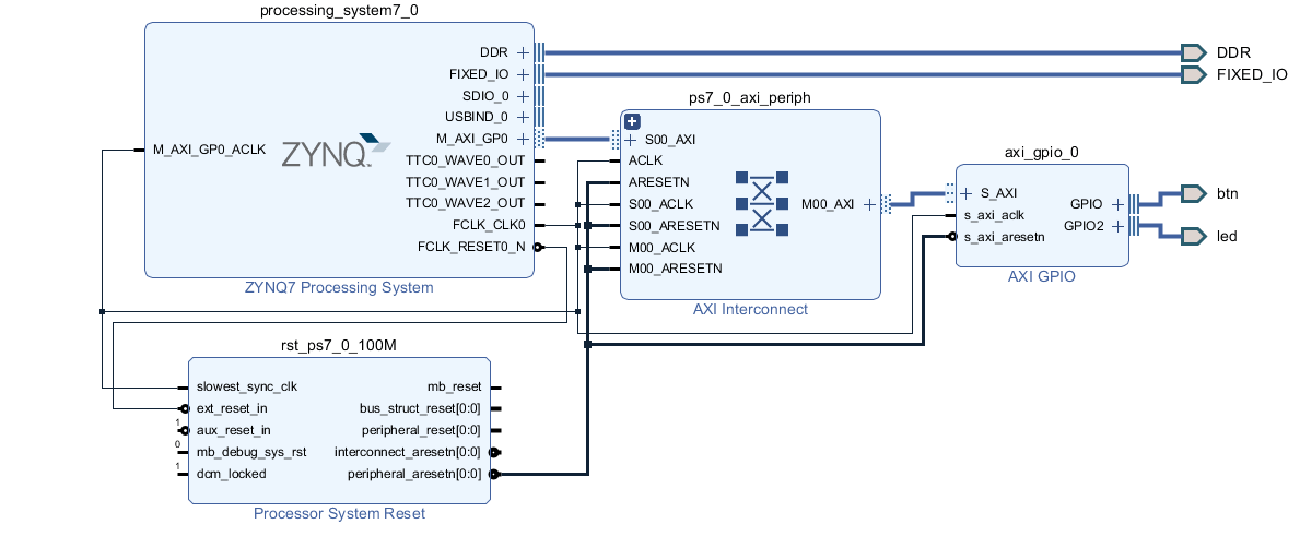
I am using the Zybo 7010 board for this project and the board files helped me auto-configure most of the Zynq PS system. Make sure you enable UART0 in the PS because that’s how we will communicate with the board when we boot it up. I have uploaded the board design tcl file which will help you recreate the whole project quite easily.
Export the hardware file and start building petalinux
The basic steps to build petalinux were shown in my previous article where we built Petalinux from scratch. Most of those steps will remain untouched except for the addition of a few extra steps. Therefore, I will only be showing the added extra steps here to avoid making the article too long.
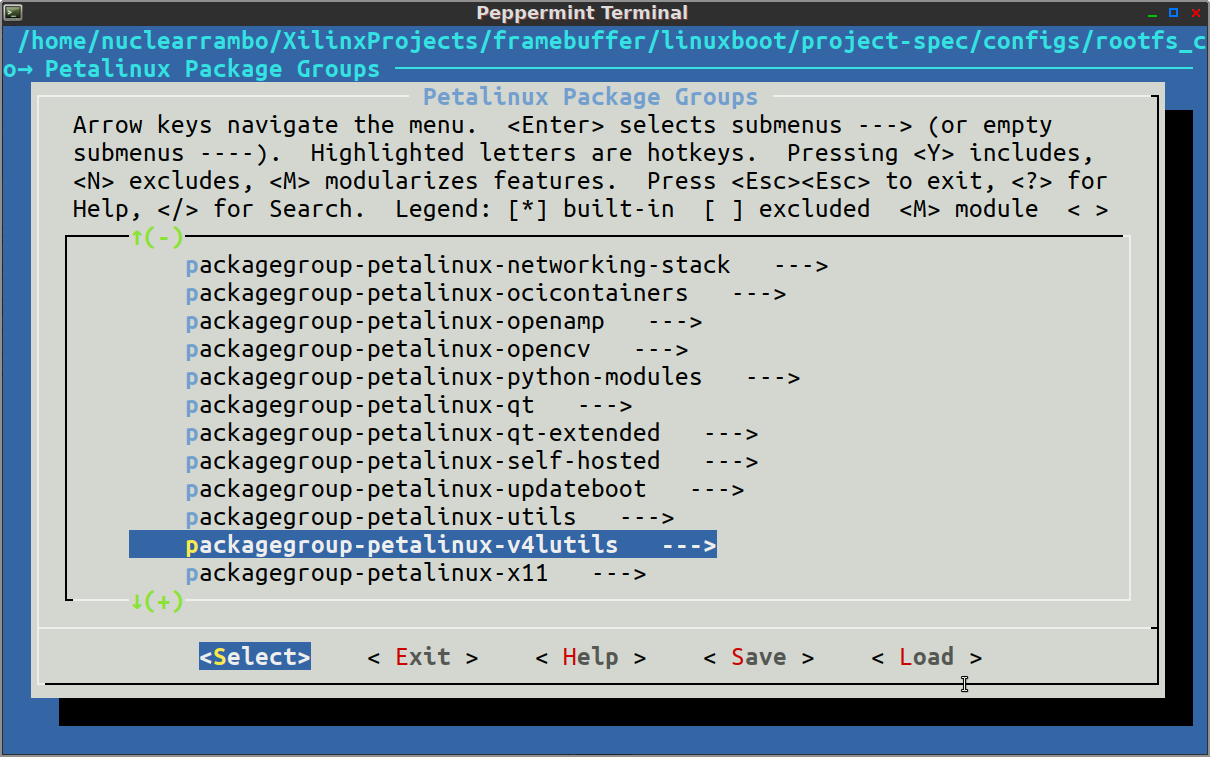
petalinux-config -c rootfs
This should open the following window where you need to select certain features.

You need to select the v4l2utils. Additionally, you may also select openCV and the rest of the features that you might consider useful.
Usually, the next step would be to build petalinux but we are going to wait because there’s something more we need to do. That something is defining the video pipeline in the device tree.
Defining the device tree
Fortunately, the base system device tree gets auto-generated by the device tree generator built scripts built into Petalinux. Nevertheless, Petalinux puts the job of defining video pipeline interconnection upon the user.
Automatically generated device tree resides in the following path:
/<project_dir>/components/plnx_workspace/device-tree/device-tree
We won’t be touching any of the files in this directory. All the files in this directory are auto-generated by Petalinux every time you build it. Edit the following file to add our video pipeline.
/<project_dir>/project-spec/meta-user/recipes-bsp/device-tree/system-user.dtsi
The system-user.dtsi file tells Petalinux about manual device tree entries. The V4L2 expects you to specify what component connects to what. In addition to that, we also specify the video format, pixel width, reset pin, port direction and so on.
|
1 2 3 4 5 6 7 8 9 10 11 12 13 14 15 16 17 18 19 20 21 22 23 24 25 26 27 28 29 30 31 32 33 34 35 36 37 38 39 40 41 42 43 44 45 46 47 48 49 50 51 52 53 54 55 56 57 58 59 60 61 62 63 64 65 66 |
/include/ "system-conf.dtsi" / { }; #include <dt-bindings/media/xilinx-vip.h> &amba_pl { v_frmbuf_wr_0: v_frmbuf_wr@43c00000 { #dma-cells = <1>; clock-names = "ap_clk"; clocks = <&clkc 15>; compatible = "xlnx,v-frmbuf-wr-2.2", "xlnx,axi-frmbuf-wr-v2.1"; interrupt-names = "interrupt"; interrupt-parent = <&intc>; interrupts = <0 29 4>; reg = <0x43c00000 0x10000>; reset-gpios = <&axi_gpio_0 1 0 1>; xlnx,dma-addr-width = <32>; xlnx,dma-align = <8>; xlnx,max-height = <2160>; xlnx,max-width = <3840>; xlnx,pixels-per-clock = <1>; xlnx,s-axi-ctrl-addr-width = <0x7>; xlnx,s-axi-ctrl-data-width = <0x20>; xlnx,vid-formats = "bgr888", "uyvy", "y8", "yuyv"; xlnx,video-width = <8>; }; v_tpg_0: v_tpg@43c10000 { compatible = "xlnx,v-tpg-8.1", "xlnx,v-tpg-7.0"; reg = <0x43c10000 0x10000>; xlnx,vtc = <&v_tc_0>; reset-gpios = <&axi_gpio_0 0 0 1>; ports { #address-cells = <1>; #size-cells = <0>; port@0 { reg = <0>; xlnx,video-format = <XVIP_VF_YUV_422>; xlnx,video-width = <8>; tpg_out: endpoint { remote-endpoint = <&vcap_tpg_in>; }; }; }; }; vcap_tpg { compatible = "xlnx,video"; dmas = <&v_frmbuf_wr_0 1>; dma-names = "port0"; ports { #address-cells = <1>; #size-cells = <0>; port@0 { reg = <0>; direction = "input"; vcap_tpg_in: endpoint { remote-endpoint = <&tpg_out>; }; }; }; }; }; |
I have practically copy-pasted my entire system-user.dtsi file for your reference. When you read carefully, the TPG has one output port that’s mentioned as tpg_out and it connects to its ‘remote-endpoint’ vcap_tpg_in mentioned in the next block of code just below it.
You must read the pl.dtsi that resides alongside system-conf.dtsi in the auto-generated device tree directory. There are times when the auto-generator script fails to identify all the properties in your hardware. For example, when I was building this system, the pl.dtsi did not mention any reset property for the TPG. Hence, I added it manually in the system-user.dtsi file.
reset-gpios = <&axi_gpio_0 0 0 1>;
Now, its time to build the petalinux system by running,
petalinux-build
This may take quite a while depending on your machine. Sit back and let it finish. Finally, when the build completes, we need to package it with the following command.
petalinux-package --boot --force --fsbl images/linux/zynq_fsbl.elf --fpga images/linux/system.bit --u-bootEventually, load the following files onto the FAT32 partition of the SD card.
- BOOT.bin
- boot.scr
- image.ub
Extract the rootfs archive onto the ext4 partition as follows.
tar -xzvf rootfs.tar.gz -C /media/nuclearrambo/root_partition/
Booting the system
While booting the system, we are interested in knowing whether the TPG, VTC and the Framebuffer get probed and initialized during boot. To be honest, I struggled a lot while getting past this stage. The error codes given out by the drivers help in debugging the problematic areas in our setup. For example, the TPG driver may give out different error codes depending on the problem. Sometimes, all you may see is an error code “-2”. The linux error code list clearly comes in handy while figuring out the error. While looking up the error codes, “-2” comes as a result of accessing an invalid directory/resource. A clear indication of non-existence of whatever the driver code was looking for. At times, I had to deal with the error “-22”; an indication of an invalid argument.
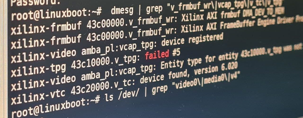
Therefore, keep an eye for errors while booting the system. Once the boot process ends, the TPG gets registered as a /dev/v4l-subdev0 entry. Whereas, the pipeline should show up as /dev/video0.
|
1 2 3 4 5 6 |
root@linuxboot:~# dmesg | grep "v_frmbuf_wr\|vcap_tpg\|v_tc\|v_tpg" xilinx-frmbuf 43c00000.v_frmbuf_wr: Xilinx AXI frmbuf DMA_DEV_TO_MEM xilinx-frmbuf 43c00000.v_frmbuf_wr: Xilinx AXI FrameBuffer Engine Driver Probed!! xilinx-video amba_pl:vcap_tpg: device registered xilinx-video amba_pl:vcap_tpg: Entity type for entity 43c10000.v_tpg was not initialized! xilinx-vtc 43c20000.v_tc: device found, version 6.020 |
Lets check whether video0, media0, v4l-subdev0 show up in our devices list “/dev/”.
|
1 2 3 4 5 |
root@linuxboot:~# ls /dev/ | grep "video0\|media0\|v4" media0 v4l v4l-subdev0 video0 |
Seems we are good to go. Apparently, theres more than half way to go across before we can actually capture raw video frames coming in from the test pattern generator. In one of the next articles, I will also describe in detail the crude debugging process that I followed to get to the point we are at. Professionals might call my methods crude and raw, but sometimes, when you have no help from anyone, YOU DO WHAT YOU MUST DO!
Conclusion
So far, it’s been good progress towards our end goal and our video pipeline now appears in the devices. In the next part, I will show you the test pattern generator configuration and maybe an attempt at capturing raw frames from the test pattern generator.
You may also check the following projects that I did around the Zybo 7010 Zynq SoC board.

Thank you. well done sir
it very useful, but can you post the part 2 of project. I really need it
Same as Huy, very sad that there is no part 2 u_U.
Were you able to capture the footage?
I didn’t continue the project. I wish to start back from where I stopped. Probably soon.