Radar on a chip – Shrinking Radars!
Whenever we hear the word “Radar”, a picture comes to mind with a rotating line across a circular display with a few objects moving here and there. This is a general perception of radars that we have after watching a few Hollywood movies. Just like all our devices are shrinking every year, so are the radars. Well, there are huge radar systems still being built but they have their own purpose.
You may have come across the term “System on a Chip” (SoC) where RAM, storage and the processor are all built on one single silicon chip and that is how it is these days if you happen to open up your tablet computer or your cellphone. SoC has made it possible to shrink our devices by eliminating the need to use separate chip for RAM, separate chip for mass storage and a separate chip for processing the data. Even the graphics processor is now embedded into the same SoC integrated chip. One chip and it takes care of everything and that is why we have super slim and super powerful smartphones available these days giving more space to have a huge battery inside.
Nevertheless, our main focus is along the same lines but with regards to radars.
Over the last several decades, as electronics has progressed and started becoming digitized, so have the radars. Huge amounts of data processing which was done using analog circuits consisting of tens of transistors, filters, frequency converters and analog signal processors is now done entirely in the digital domain. With increasing processing power and shrinking size of computing equipment, it is possible to process the signals in real-time on single chip multi-core digital signal processors. But we need to understand what kind of signals are processed on the digital domain and we can only come to understand that upon looking at the basic block diagram of a radar.
Inevitable analog components
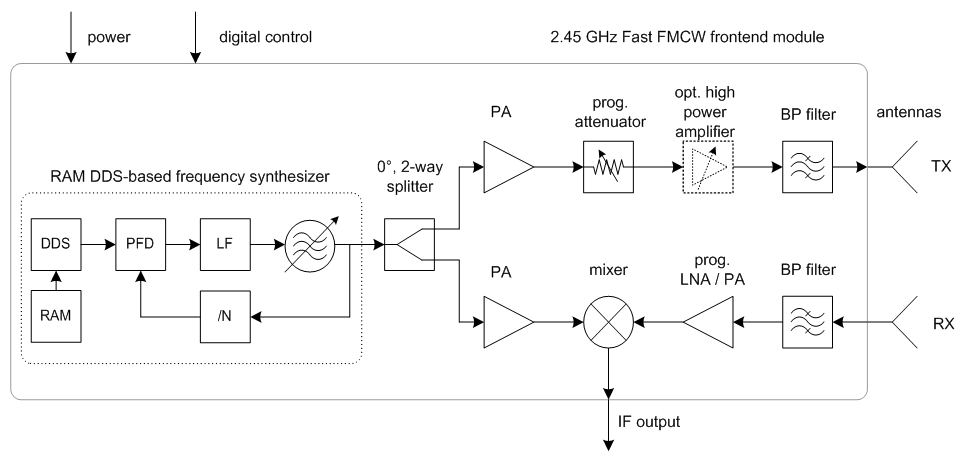
Figure 1 only shows the front end module, that is basically where the radar pulse is transmitted or received from. Depending on the radar application, the radar is designed to output frequencies ranging from as low as 100MHz to as high as 100GHz.
Abbreviations used in the block diagram:
|
1 2 3 4 5 6 7 8 9 10 11 12 13 14 15 16 17 18 19 20 21 |
RAM: Random access memory PFD: Phase frequency detector DDS: Direct digital synthesizer (Use to generate any type of wave) LF: Low pass filter /N: divide by N Prog. Attenuator: Programmable attenuator BP: Band pass filter TX: Transmitter RX: Receiver LNA: Low noise amplifier PA: Power amplifier |
As shown in the Figure 1, most of these components operate at the final frequency the radar is designed to transmit. Suppose it is designed to operate at 24GHz, it will be difficult to handle these signals digitally directly at that frequency. Instead, something called as up conversion is used.
Using the principle of frequency mixing, we can produce a higher frequency from a lower frequency. This is done with help of a mixer.
Up conversion to high frequency
The DDS generates a low frequency, say 100MHz signal which is then simply multiplied with the fixed high frequency carrier, say 24GHz. The result is 24GHz + 100MHz = 24.10GHz which is then finally transmitted. The power of the signal is still quite weak. If we want to look at targets located at 20kms away, we need to transmit a high power signal and that is done with the PA (Power amplifier).
When the transmitted signals hits the target and reflects back, it needs to be picked up by the receiver. The received signal is always very very weak and needs to be amplified. Again, this is something that needs to be done in analog domain because digital circuits cannot directly handle such high frequency signals yet. LNA and a bunch of filters make the signal ready for “mixing”. Mixing again converts the signal frequency down to something that can be handled by the digital receiver and this is labelled as “IF” (Intermediate frequency).
This is where digital signal processing plays a huge role. Once IF is converted to digital signals, complex digital signal processing algorithms can take over and extract the target’s size, speed, direction, distance and so on. All these algorithms required large transistor circuits in the past, but with signal processors that has been eliminated and replaced with processor circuit boards as small as your set top box sitting on your TV. Just to point out the fact, your TV set top box is well capable of processing radar signals and all you need to do is feed it with appropriate signal.
Such signal processing boxes are known as Digital receivers. This has brought down the size of radars tremendously. Again, size of the front end is what makes the radar quite bulky and that too can be shrunken further and designed to fit on a silicon chip!
Power = size!
Military radars and weather radars are something that are used to detect targets located at several kilometers away. To successfully detect those targets at such large distances, you need more power. More power equals, heavier amplifiers that may require its own cooling system which makes radars as huge as a truck.
But, if you are looking to detect objects just a few meters away, you can be well off using single chip radars which are making its way through into consumer markets.
Like I said, power is proportional to size, similarly, size is also inversely proportional to frequency.
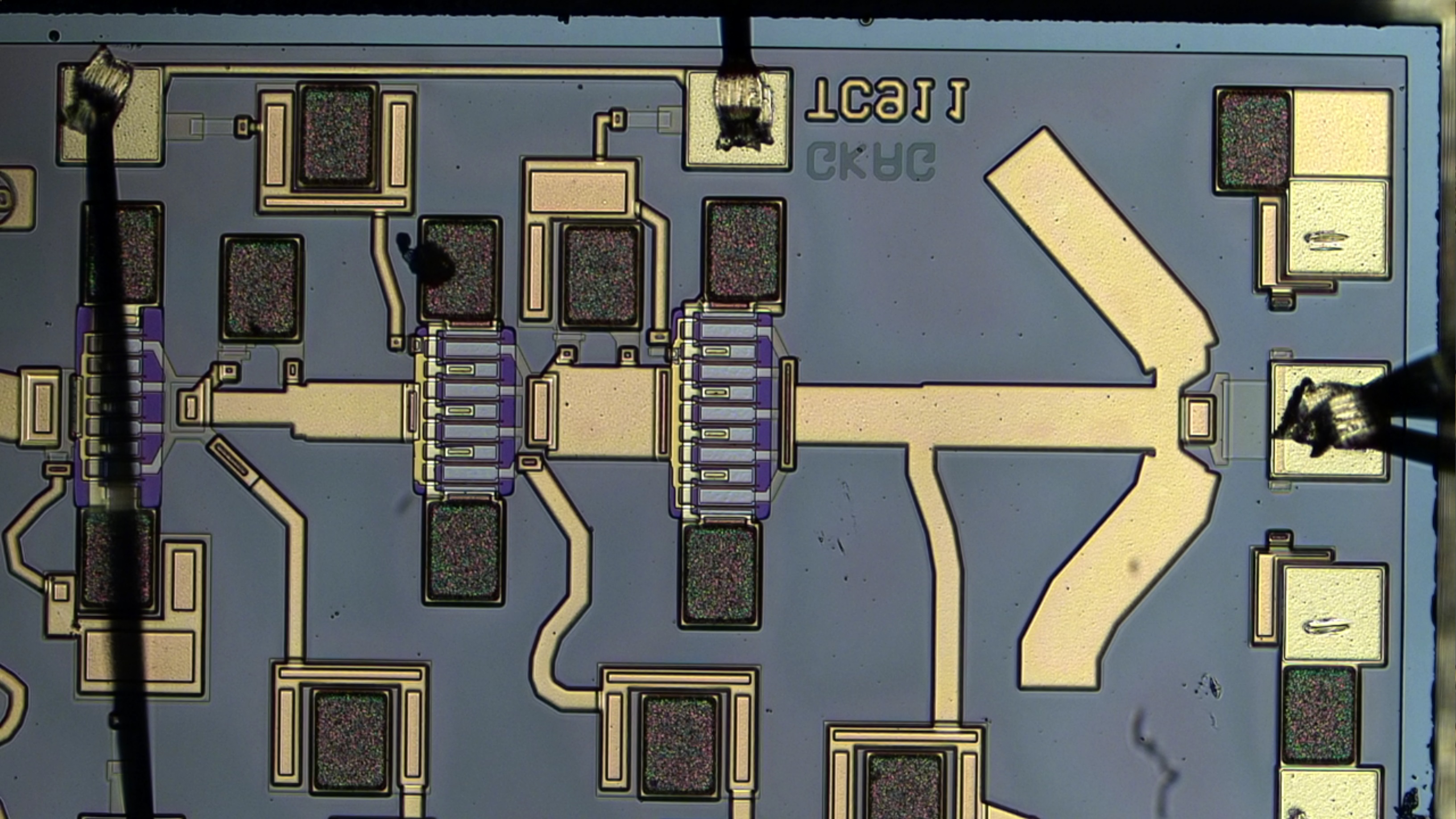
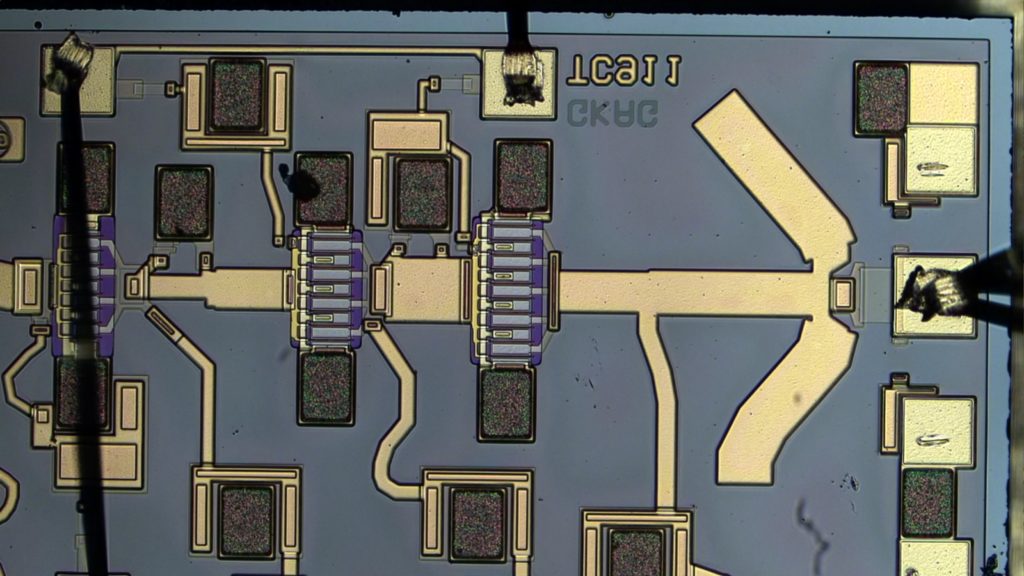
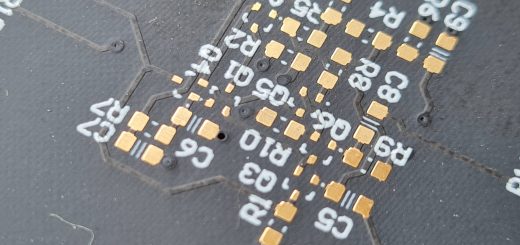
The higher the frequency, lower the component size. At 66GHz, the filters, power amplifiers are so tiny, you need a microscope to look at them. Here is an image of just one of the sections inside a LNA in the receiver section and it is designed to operate at 35GHz.
Google ATAP’s Project Soli
[2] Project Soli is just one of the many “Radar on a Chip” projects undertaken by several research organizations world over.
Just as we saw, there are analog amplifiers and mixers and then there is a digital receiver to process the signals. Digital receiver simply being a general applications process with lot of processing power that can be programmed like any other processor in the world, we are simply left to design an equivalent analog front end (similar to one shown in the Figure 1).
Project Soli integrates a signal processor and the analog front end together and the result is a “Radar on a chip” operating at a whopping 66GHz.
If you haven’t seen the video, go ahead and click on the link:
Others in the game
Google is not the only one in the game of one chip radars. Company called Omniradar has been making single chip radars for a while and they have even specified certain applications where it can be used.
The following image [3] from Omniradar’s website is enough to explain some of its applications!
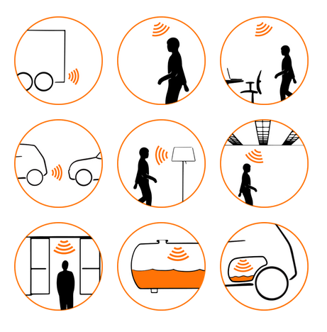
These tiny radars can come extremely handy in the future of Internet of Things where everything will be connected to a single network. It can be used for automatic turning on and off of lights in a room, detecting whether you are sleeping so that the computer can automatically turn off the lights and the TV in the room. YES! These radars can detect what you are doing because they are very sensitive. Although that is only possible if you have an appropriate algorithms running on the digital signal processor. Applications are tremendous!
ADAS – Advanced Driver Assistance System
ADAS has been on the rise in recent years. Some time ago, we had an article in the Exponent Group of Journals for Electronics (December 2014) which talked about how all the components inside any given vehicle are interconnected over the CAN bus.
Just another set of electronic components that have been getting installed in modern cars are “Radars”. Radars installed on the front, the back and on the sides to help the driver drive the vehicle [4] safely by maintaining proper distance with other vehicles on the road. It also comes handy while parking.
ADAS radars are quite tiny and they operate in the automotive band which is at 75GHz.
Conclusion
Watch out for tiny radars popping up in phones, gaming consoles, smart watches, modern vehicles, railways and much more. Radars are used everywhere and with modern signal processors and nanotechnology on the rise, they are going to shrink further!
References:
|
1 2 3 4 5 6 7 |
[1] Alfred Binder, Gudrun Bruckner and René Fachberger (2011). SAW Transponder – RFID for Extreme Conditions, Deploying RFID - Challenges, Solutions, and Open Issues, Dr. Cristina Turcu (Ed.), ISBN: 978-953-307-380-4, InTech, DOI: 10.5772/17526. [2] Google ATAP. Welcome To Project Soli. YouTube. 29 May 2015. Web. [3] OmniRadar. Applications. Web. [4] Robertson. Brett. Reuter. Increasing Automotive Safety through Embedded Radar Technologies. Freescale.com. Web. |
Want to read more of these articles? Head right away to the Exponent Group of Journals where you can read more of my articles.


Very informative lay man can also understand.
Very interesting and informative article. All the best salil.