
DRA818V VHF band transceiver – Part 1
Necessity to stay connected with others is growing by the day. In cases when mobile network is out of reach and a message needs to be relayed or received, ham radio can prove to be quite helpful. Let us not get into the details as to why I am making this ham radio transceiver. The purpose of this post is to get into the technical aspect of it.
There is a chip for every purpose these days. The RDA1846 has everything that is needed for transmitting and receiving a VHF band frequency modulated signal. It has amazing sensitivity that goes all the way down to -120dBm, it can pump out 1W of RF power and it does Frequency modulation. The same RDA1846 goes inside the DRA818V module. It needs AF (audio) input and it gives AF output which can be fed into the speakers. The frequency at which the module needs to tune itself is set over a UART port with the help of AT commands.
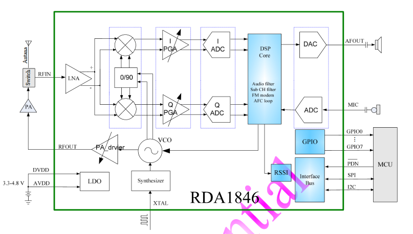
Block diagram of RDA1846
RDA1846 is such an amazing chip. It has an RF front end with Low noise amplifier, I/Q mixers, two ADCs, and further down the line is a DSP core that does the job of frequency modulation and demodulation. Apart from that, there is an integrated frequency synthesizer that acts as a local oscillator for the mixers. We cannot forget about the 30dBm Power amplifier that draws a great deal of current while transmitting. It is just too much to go on about the internals of the chip and I will let you read the datasheet in that case.
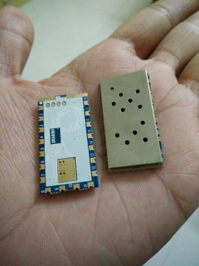
A couple of DRA818V modules
Getting the chip up and running is our first task at hand. A simple PCB containing a microphone amplifier and an audio amplifier is all that we need to build. We will also need to bring out a few pins on the header which will be useful for sending commands from the UART port.
Gathering information for our first PCB prototype
This part is quite easy as the datasheet is quite to-the-point and short. DRA818V has a UART interface over which we need to send commands for the module which in turn modifies the frequency it is tuned to, the AF output volume level, AF filter settings and as such.
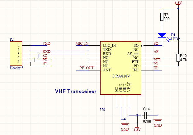
DRA818V
DRA818V operates at 3.3V and may be powered up with a maximum of 4.5V. There are a couple of pins that need to be tied to 3.3V or Ground to get the module working. First one is the PTT (Push to Talk)(Pin 5) pin which when left floating will put the module in Transmit mode whereas, tying it to ground will switch it over to Receive mode. We need it to be in Receive mode by default and needs to be pulled to ground (0V) when we intend to transmit voice. A simple tactile switch does this job for us.
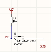
Push to talk
The power down pin needs to be pulled high at 3.3V to keep the module working. A Squelch output goes high (3.3V) when signal is receive above certain power level. Connecting this pin to a LED will give us an indication of presence of signal. This Squelch line will also help us turn off the output audio amplifier when no signal is being received and this will help us save power.
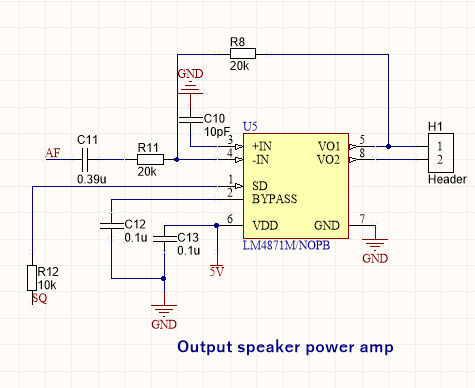
Output audio amplifier with LM4871
The input to the module is from a microphone amplifier built from a LM358 operational amplifier. Being powered from a single 5V supply, the input signal needs to be pushed and centred at 2.5V for preventing the negative peak from cutting off. The output of the amplifier is fed into the AF input of the DRA818V module.
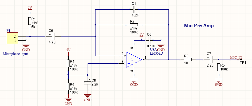
Microphone amplifier
We are still missing a big part of the circuit. The RF circuit. The single major thing that is responsible for pumping the radio signal out and receiving the radio signal. DRA818V produces several other frequencies called harmonics while it transmits. The harmonics are resultant of the mixing process. These frequencies lie around center frequency and it can cause distortion on other bands. To prevent this from happening, a simple low pass filter does the job for us.
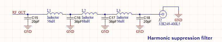
Harmonic suppression filter
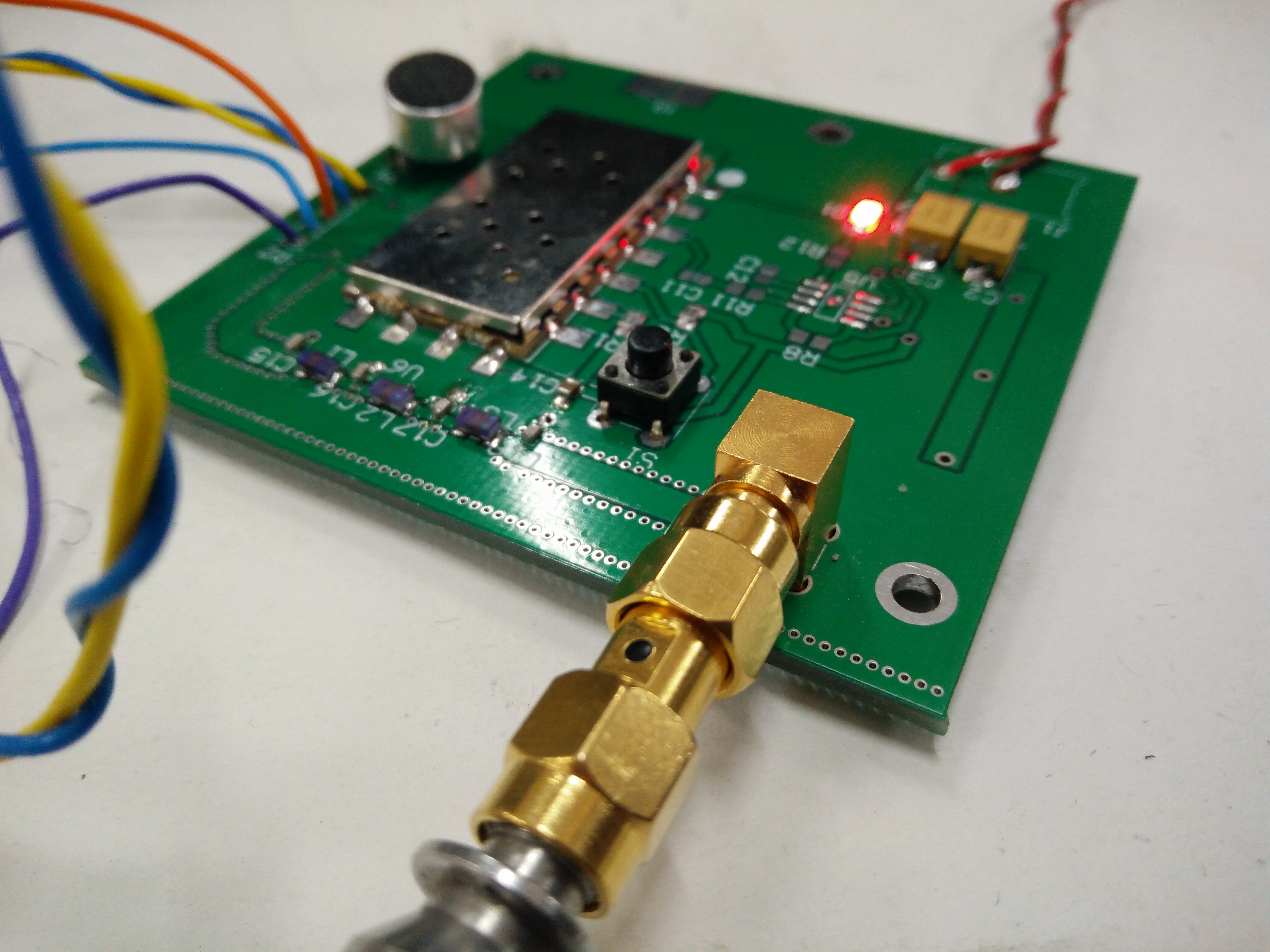
With this done, I designed a PCB that looks like this.
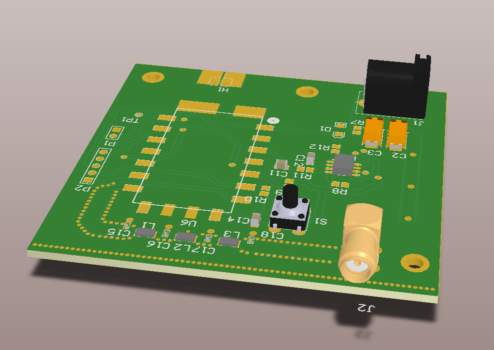
DRA818V PCB
And the real thing looks ….quite identical to it.

DRA818V PCB Looks identical right?
The first test
The first task is to establish a UART connection. For this, I used a TI Connected launchpad which I had lying on my table. The launchpad operates at 3.3V as well. You might as well get away with using an Arduino for connecting to the module since, the datasheet says that the UART pins on the DRA818V module are TTL tolerant.
|
1 |
AT+DMOCONNECT |
…is used for assuring ourselves that the module is operational and indicates that we can send some more commands to change the behaviour of the module. If it responds back with…
|
1 |
+DMOCONNECT: 0 |
…it means that everything is fine.
Let us do something else…
|
1 |
S+145.0000 |
…internally detects existence of power at 145.0000MHz frequency and responds with the following response…
|
1 |
S=0 OR S=1 |
S=0 if it detects presence of 145MHz carrier frequency and S=1 if it does not.
I am still not sure whether I was doing everything right, because no matter what signal I fed, it just kept giving me S=1 which was not correct.
|
1 |
AT+DMOSETGROUP=0,145.0000,145.000,0000,1,0000 |
The DMOSETGROUP command tunes the module to receive and transmit 145.0000MHz frequency. There are several numbers in the command for which you can find the details in the datasheet. For our test, we need the first parameter to be 0 indicating the module to expect FM modulation with 12.5kHz deviation. The second and the third parameter indicate transmit and receive frequency which is at 145.0000MHz.
With the configuration done, I hooked up the RF output of the PCB to the spectrum analyzer which plots frequency vs. power as seen in the image below.
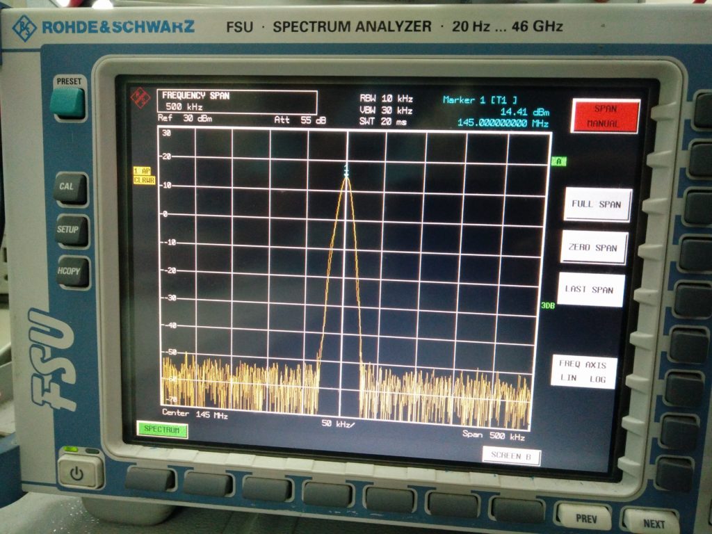
DRA818V output on spectrum analyzer
To check if the receiver also works as expected, I need the LM4871 audio amplifier which I still haven’t been able to obtain as you can see the PCB image where the solder pads are left open for the same reason.
Conclusion
Nevertheless, the purpose of this test was to gain confidence in the DRA818V module which will be used as a HAM radio receiver, or may be even a transmitter. I have some interesting ideas that I intend to implement. For example, using a cheap microcontroller interfaced with a rotary encoder that will relay corresponding commands for tuning on to frequencies. A nice PTT button which can be used a walkie talkie and to make things even better, a cool enclosure to house it all.
I will be posting the second part of this article series explaining the outputs of the receiver. For example we will dive deeper into the analysis of the entire circuit board and how well it does the job.


Hi, I am interested too on these module, can you know me your progress.
I am interested in build a simple VHF HAM repeater -600Khz
How selective is this module to adyacent transmisions ??
Can it be used on a high RF noise environment. FM broadcast near repeater location.
We use cavities too.
Regards
How much range you’d got with this transceiver??
I really do not understand the meaning of:
A) First one is the PTT (Push to Talk)(Pin 5) pin which when left floating will put the module in Transmit mode whereas, tying it to ground will switch it over to Receive mode. [–> Ground is receive]
B) We need it to be in Receive mode by default and needs to be pulled to ground (0V) when we intend to transmit voice. [ –> Ground is transmit]
Sorry, what now: ground for transmit or receive? Don’t drink and write…
Is there the part 2?
Yes, I havent posted about it here. I may do it since you have reminded me about it.
bump!
Hi nuclearrambo and thanks for this article.
Just out of curiosity asking about the microphone amplifier part, is this amplifier necessary for the setup?
Referring to DRA818X datasheet(http://www.dorji.com/docs/data/DRA818U.pdf) page 8, for the typical application circuit there is no Mic amplifier!
Regards.
You are correct. I realized that few weeks ago when I had to deal with a newer version of this module (SA868). There is no need of a mic amplifier.
Hi,
When comes part 2 ?
Hello Salil,
I have noticed that my modules “cut out” received audio if the deviation is greater than 3 KHZ. The squelch setting has no affect on preventing this. Have you notice this on yours? I may have a bad module or a “floor sweeping” that did not pass quality tests and was sold to hobbyist.
The squelch function works just the way it should. Deviation more than 3kHz shouldn’t be a problem. It should work all the way till 30 or 50kHz. As far as I remember, I have tested 75kHz deviation with good results.
Is it possible to get Gerber file of your PCB by chance?