
Transmit channel phase shifting on PlutoSDR
The PlutoSDR Rev C brings out both the transmit and receive channels. Thus, making it an even more capable device, especially for advanced RF stuff. A phased array is an advanced RF application that immediately comes to mind. Phase shifting on the Tx and Rx channels is an essential operation for the phased array systems. Today, I am not really going to dive into the phased array stuff but rather do a very primitive phase-shifting operation between the two transmit channels of the PlutoSDR.
Understanding the transmit chain
Observe the transmitter chain of the AD9361 shown below. The baseband IQ gets fed into the chip over the CMOS/LVDS interface over either SDR or DDR interface. This data goes right into the FIFO and fed forward into the rest of the chain. The baseband IQ data passes through the respective digital signal processing blocks consisting of a chain of filters before ending up at the input of DAC. The DAC operating at a higher clock rate produces an analog baseband signal. Further, this signal is filtered by tunable bandwidth filters lined up ahead of the DAC. There are two separate chains for processing I and Q independently.
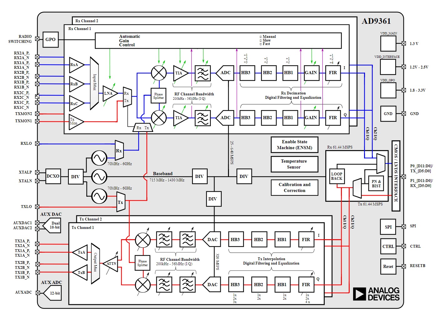
A PLL serves as a local oscillator (LO) for the IQ mixer. The Phase splitter ensures the LO going to each mixer is 90° shifted with respect to each other. Further in the chain, a variable attenuator allows output power level control.
A little math and a little understanding of mixers…
This is an SDR that we are working with and as the name suggests, the software we write can control what goes into the IQ mixer. The output of the IQ mixer depends on two inputs, the LO and the baseband input. Usually, in the case of transmitters, the LO is a higher frequency whereas, the baseband signal has a lower frequency component associated with it. Both are mixed and that results in the baseband signal appearing around the carrier frequency. The standard mixer equation looks something like this.
\(cos(\omega_1)cos(\omega_2) = \dfrac{cos(\omega_{1} + \omega_{2})}{2} + \dfrac{cos(\omega_{1} – \omega_{2})}{2}\)
Now, assume the two signals have the same frequency.
\(cos(\omega_1)cos(\omega_1) = \dfrac{1}{2} \times (1+cos(2\omega))\)
The \(\dfrac{1}{2}\) portion is indicative of a DC shift while the \(cos(2\omega)\) indicates the doubling of output frequency. It’s this DC shift we are interested in.
If, instead of mixing the LO with a different signal of different frequencies, we mix it with a DC offset. That should result in phase shift at the output of the mixer.
The best example is the BPSK generator circuit which feeds binary symbols (1 or -1) at the baseband input of the mixer. Correspondingly, a carrier signal of certain frequency works as LO input to the mixer.
\(cos(w_{c}t)\) the carrier frequency fed to the mixer gets mixed with the baseband binary data which is either +V or -V.
When multiplied with +V (assuming it as logic 1), we get a sinusoidal waveform. On the contrary, when its multiplied with -V (assuming it as logic 0), the result is an inverted sinusoidal waveform.
This operation is known as Binary phase shift keying and it’s a popular digital modulation form for transmitting digital data. The BPSK, as we saw, has two phases that represent either logic 1 or logic 0.
If we use another carrier with \(90^\circ\) phase shift and apply BPSK on that. Finally, by adding the first and the second carrier, we obtain what’s known as Quadrature phase shift keying (QPSK).Now, the resultant waveform can comprise 4 phase shifts; \(45^\circ , 90^\circ, \ 180^\circ \ and \ 270^\circ\)
Similarly, with the quadrature carrier, we should be able to generate any phase angle we desire and not just the four mentioned above.
Final math equation…
I followed the following equation to generate the base band I (in phase) and Q (quadrature) waveforms.
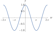
\(I_{bb} = \cos{2\pi ft + \theta } \)
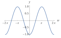
\(Q_{bb} = \sin{2\pi ft + \theta } \)
Here,
\( f = 0 \ and \ \text{theta} = phase \ in \ radians\)
Finally, inside the AD9361, the I and Q baseband mixes with the in-phase and quadrature carriers respectively.
\(I_{rf} = \sin{\omega_{c}t} \times I_{bb} \)
\(Q_{rf} = \cos{\omega_{c}t} \times Q_{bb} \)
Finally,
\(OUT_{rf} = I_{rf} + Q_{rf}\)
produces the final transmit waveform at the output port 1.
I also generated a second waveform at port 0 of the plutoSDR that had \(\theta = 0\). This signal acts as a reference channel.
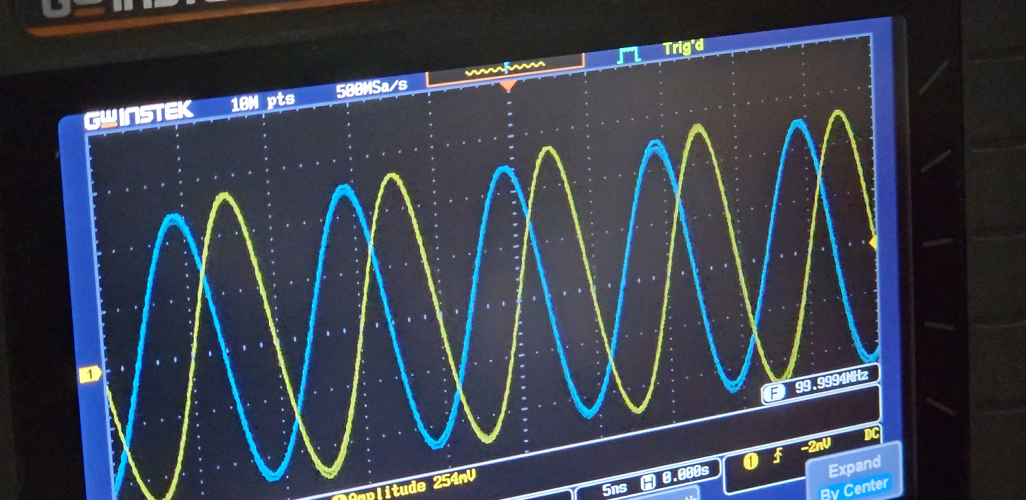
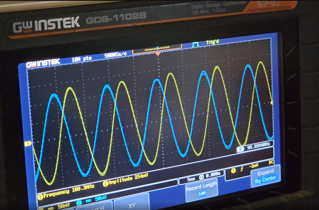
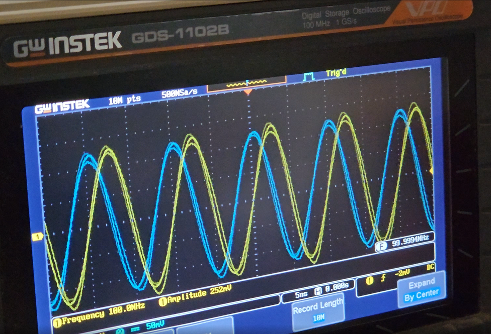
To conclude, I observed both the signals, reference at port 0 and phase shifted at port 1 on an oscilloscope.
I own the GwInstek GDS-1102B 2 channel 100MHz oscilloscope I purchased several years ago. Therefore, I can only view the waveforms up to 100MHz. Be assured this technique definitely works at higher frequencies. Make sure, the cables you use are equal length since we do not want to add any extra phase shift with unequal cables. Speaking of cables, do check out one of my previous articles on measuring cable lengths with the NanoVNA. In another article, I explain the process of making phase-matched cables with the same NanoVNA.
The Python script
|
1 2 3 4 5 6 7 8 9 10 11 12 13 14 15 16 17 18 19 20 21 22 23 24 25 26 27 28 29 30 31 32 33 34 35 36 37 38 39 40 41 42 43 44 45 46 47 48 49 50 51 52 53 54 55 56 57 58 59 60 61 62 63 64 65 66 67 68 69 70 71 72 73 74 75 76 77 78 79 80 81 82 83 |
import adi import time import matplotlib.pyplot as plt import numpy as np # Create radio sdr = adi.ad9361(uri='ip:192.168.2.1') samp_rate = 30.72e6 # must be <=30.72 MHz if both channels are enabled num_samps = 2**18 # number of samples per buffer. Can be different for Rx and Tx rx_lo = 100e6 rx_mode = "slow_attack" # can be "manual" or "slow_attack" rx_gain0 = 0 rx_gain1 = 0 tx_lo = rx_lo tx_gain0 = -10 tx_gain1 = -11 '''Configure Rx properties''' sdr.rx_enabled_channels = [0, 1] sdr.sample_rate = int(samp_rate) sdr.rx_lo = int(rx_lo) sdr.gain_control_mode = rx_mode sdr.rx_hardwaregain_chan0 = int(rx_gain0) sdr.rx_hardwaregain_chan1 = int(rx_gain1) sdr.rx_buffer_size = int(num_samps) '''Configure Tx properties''' sdr.tx_rf_bandwidth = int(samp_rate/2) sdr.tx_lo = int(tx_lo) sdr.tx_cyclic_buffer = True sdr.tx_hardwaregain_chan0 = int(tx_gain0) sdr.tx_hardwaregain_chan1 = int(tx_gain1) sdr.tx_buffer_size = int(num_samps) # Example read properties print("RX LO %s" % (sdr.rx_lo)) # Program the Tx with some data fs = int(sdr.sample_rate) fc0 = int(0) fc1 = int(0) phase = 90 while True: for phase in np.linspace(0, 360, 36): N = 2**16 ts = 1 / float(fs) t = np.arange(0, N * ts, ts) i0 = np.cos(2 * np.pi * t * fc0) * 2 ** 14 q0 = np.sin(2 * np.pi * t * fc0) * 2 ** 14 i1 = np.cos(2 * np.pi * t * fc1 + phase*(np.pi/180)) * 2 ** 14 q1 = np.sin(2 * np.pi * t * fc1 + phase*(np.pi/180)) * 2 ** 14 iq0 = i0 + 1j * q0 iq1 = i1 + 1j * q1 sdr.tx_destroy_buffer() sdr.tx([iq0, iq1]) # Send Tx data. print(np.mean(iq1)) time.sleep(1) # Collect data for r in range(20): # grab several buffers to give the AGC time to react (if AGC is set to "slow_attack" instead of "manual") data = sdr.rx() Rx_0=data[0] Rx_1=data[1] Rx_total = Rx_0 + Rx_1 NumSamples = len(Rx_total) win = np.hamming(NumSamples) y = Rx_total * win sp = np.absolute(np.fft.fft(y)) sp = sp[1:-1] sp = np.fft.fftshift(sp) s_mag = np.abs(sp) / (np.sum(win)/2) # Scale FFT by window and /2 since we are using half the FFT spectrum s_dbfs = 20*np.log10(s_mag/(2**12)) # Pluto is a 12 bit ADC, so use that to convert to dBFS xf = np.fft.fftfreq(NumSamples, ts) xf = np.fft.fftshift(xf[1:-1])/1e6 plt.plot(xf, s_dbfs) plt.xlabel("frequency [MHz]") plt.ylabel("dBfs") plt.draw() plt.show() |
Do read my previous article where I explain the basics of using PlutoSDR using Python.
Hope you like the content. Don’t forget to leave a comment because that encourages me to write more frequently.
Voice of the people