
Very simple High voltage converter – Boost converter
The most simplest circuit which can convert low voltage to high voltage is the Boost converter circuit with high efficiency.
The simple low voltage to High voltage converter requires an inductor, diode, a high speed switching device and a storage element. All this can be achieved with a simple setup shown right below.

The arduino generates PWM waveform which is used to drive the MOSFET. The duty cycle of the PWM plays an important role in defining the amount of voltage you will be getting at the output.
The working of high voltage converter (boost converter):
1. When PWM is turned off
When the MOSFET is turned off, no current will be flowing through it, but the current will be diverted from the supply, through the diode, into the capacitor. This will charge the capacitor to the supply voltage. In this case, we are not getting any kind of step up in voltage.
2. When PWM is turned on
During the ON time of the cycle, the MOSFET turns on and starts conducting. Since inductor poses no resistance to DC current, large current flows through the MOSFET. This large current then becomes constant at some point during the ON time of the cycle. Due to the property of inductor, the energy is stored in its magnetic field around it.
During the OFF time of the cycle, MOSFET turns off and no conduction can take place. Due to the property of inductor it blocks any change in current. Because of this, the energy stored in its magnetic field is released. This creates high current. But since the MOSFET is turned off, the large current flows through the diode and charges the capacitor.
When the whole process is done fast enough, we are able to achieve a large voltage at the output.
In this experiment, I have used an old inductor from switch mode power supply that I found in the computer’s monitor. So I don’t know the value, but it is definitely greater than 200uH. IRFP450 MOSFET (HEXFET as they call it) can carry 14 amperes of current, and has a very very low drain to source resistance. The reason for using such a large MOSFET is, it does’t heat up. If you use a MOSFET with large drain to source resistance, you are going to get a lot of heat, this increases the possibility of destroying the transistor (I already destroyed like 4 expensive MOSFETs)
MOSFETs are very sensitive to heat and over voltage, so please take care that you do no exceed the specifications. My advice would be to obtain MOSFETs from old power supplies. You can also get a good number of high voltage fast response diodes from those old circuits.
I suggest you to build this circuit and try out different values of inductor and PWM. Here is a small arduino code used for generating PWM with On time of 50 uS and OFF time of 15 uS.
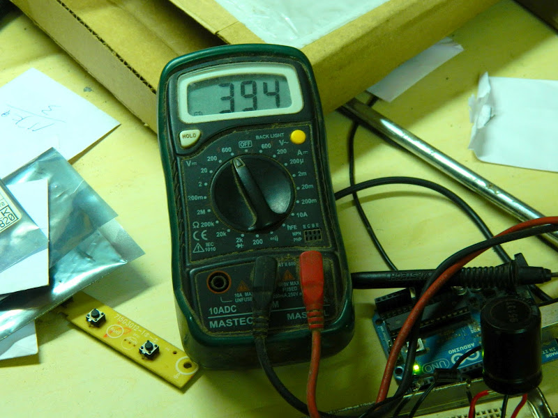
When this PWM configuration is used with my circuit it can yeild upto 394 V. I did not go beyond that, because the capacitors I have used are limited to 400V and so is the diode. So it is better to be safe below the range.
//Program for generating PWM for the boost converter
void setup()
{
pinMode(2,OUTPUT);
}
void loop()
{
digitalWrite(2,HIGH);
delayMicroseconds(50);
digitalWrite(2,LOW);
delayMicroseconds(15);
}
Instead of using arduino, you can also use timer IC or specialised PWM driver ICs.
Here are some of my circuit setup pictures.
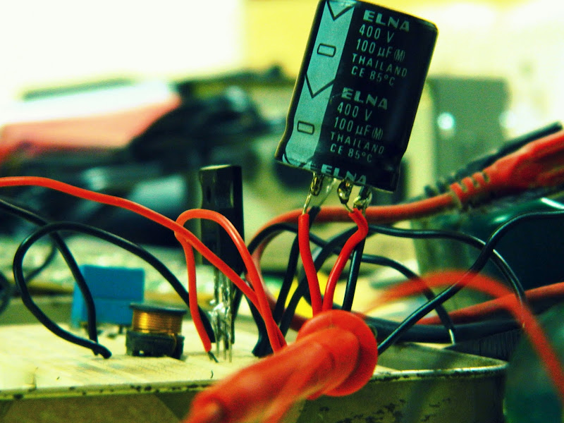 |
| From Pictures |
 |
| From Pictures |
In this simple way I have successfully built a high voltage boost converter
NOTE: Use different power supplies for the inductor and USB power supply for arduino. Using a common power supply for both, arduino and boost converter will not work out. Boost converter draws in a heavy current, so never power this circuit from USB, you will destroy the USB forever!
I have created a simple circuit involving Timer 555. The PCB layout and the schematic are below:


Thanks for your nice experience to share with us. Really awesome article with plenty of informative things to be known for us.
have u simulated the same circuit? if yes, using matlab?
No, I have used Multisim for this simulation. Although multisim or any kind of simulation didn’t work out for me. So I went to test it in real world. Took about 5-6 attempts to get this working.
i have two different voltage sourses, if i am using inverter , stepup transformer and opamp i will increse my one voltage sourse as required voltage level now can i parallel my batteries.it is possible or not give me a solution for this question?
What do you mean you are using inverter and opamp? Please send me a circuit diagram so I can have a better understanding what you are trying to do.
hai..
how much power was your supply for circuit from your electric source?
hai..
how much minimum power that you used for circuit from your electric source?
I used a 5V, 500mA source for this circuit. Used an additional 5V supply to operate the Arduino/oscillator.
I have a project to provide power using alternative energy
I want to use solar panels with 12-volt battery and a circuit that I want to run manufactured Muthur will be connected to a pump water in areas that do not reach them the power supply.Converter 12 to 120 or 100 2a.Only parts ic. Mosfet. Coil,12 to 47 DC to DC 3amp it is ok
This is my problem I have no problem raising the voltage only how to control my amps and use what I needI need a circle to convert 12-volt to 80 volts at least 3 amperes or more with the stability of the Volt.
.Is there a way to carry more than mosfet effort waza there was no Mosfet I have the same specifications
Waza I had a MOSFET device with bears and there is no effort to like him you can connect the two MOSFET to withstand high voltage or What is the appropriate method.
I have a 55-volt MOSFET bear 110 AMP Do Is there a way to bear the biggest volt 80 volts, for example,
ic uc3845 mosfet irf3205
What are the sv1-x pins connected to ? I’m trying to use this to power a coilgun for a personal project using a 5V source regulated from a 12V Source and I would like to take my 5V to 400V-600V. My goal is to only have a 5V input and a 400-600V output from this circuit.
SV1-1 -> 5V, SV1-2 and SV1-4 -> GND and SV1-4 -> 12V. You can definitely produce 400V+ from this circuit, just make sure the 12V supply is able to provide enough current.
Hi Nuclearrambo! Thanks for sharing this circuit with us. I noticed that it doesn’t have any regulation on it. How do you ensure that the output voltage does not rise to dangerous levels (i.e. beyond the maximum voltage of the output capacitor)? When I simulate such a circuit, the output voltage just keeps rising and rising…
You are right, there is no feedback to keep the output voltage in check.
You can easily have a feedback with a voltage divider which will give out output voltage reading in range of 0 to 5V or so. Give that to the ADC of some microcontroller e.g. Arduino and with that control the switching.
Nice Project Page! I’m presently working on the 555 version. For R1 and R4, using 100K potentiometers so to tune for the best output and stability. And yes, circuit with a 12Volt (9amp) SLA battery, I instantly got 397volts on the pins of the output electrolytic capacitor (rated at 450V max). The object I am trying to reach is the proper tuning of the switching at the Mosfet so to be in resonance with the inductor. Output cap charges up in about 5 seconds. I’m using a 100 ohm resistor between pin 3 of the 555 to the Gate of the Mosfet, still playing with the best value. Thanks for your posting, it was good reference for the circuit I was already in the process of building.
The first time I tried with 555 didnt work well probably because 555 didnt have enough driving capacity to drive the MOSFET’s gate? I never bothered with it and went ahead with Arduino and it worked. Let me know how it goes on for you.
Thank you so much. I’ve realized your circuit with a feedback to stabilize the voltage output and now I’ve 400V from 5V.
The global quiescent current (considering pro mini too) is about 10-15mA.
I’ve used 6 diodes in series 1n4148, 2 capacitors in parallel of 10nF @ 1kV, inductor of 220uH, and a capacitor of 1000uF between 5V and GND to stabilize the circuit
That is really impressive. Post a video for everyone to see!
Would it be possible to have the schematics for the circuit, please?
can you post schematic pleasE?
NR
I would like to use this circuit for some electroporation research I’m doing so I need to make sure current is really low (<1mA) or my cells will die. I'm a biochemist so I don't understand electronics, so do I merely make sure the input supply is current limited?
Thanks
Hi, could you please explain where is on your schematic INPUT of low voltage and where is an OUTPUT of 400 Volts
SV1-1 -> 5V, SV1-2 and SV1-4 -> GND and SV1-4 -> 12V. You can definitely produce 400V+ from this circuit, just make sure the 12V supply is able to provide enough current.
This is a really old post. I might make a better version of this some time.