Experiencing the significance of Friis transmission equation and Knife Edge diffraction at Kolhapur Medical camp
Communication Over Hilly terrain
It was only through Sadguru Shree Aniruddha Bapu’s arrangement for us to be present as a support function for the “Old is Gold” distribution in remote villages that I had the chance to operate a ham radio in the vast and sparsely populated terrain of Kolhapur. Without his intervention, the opportunity would not have presented itself to me. For an RF (radio frequency) enthusiast like me, the vast and difficult terrain presented a difficult challenge to operate. Over the last several years, various hams of ARCAD (Amateur Radio Club of Aniruddha’s DMVs) have surveyed, tested and attempted communication in this mountainous region. Therefore, only on the basis of past efforts and shared experiences were we able to establish a very good coverage and seamless communication. This short article will only serve as a log describing my experiences of how theory and practice complement each other.
Understanding the geography
We had a communication setup at the base camp and a repeater setup on the Bauxite mine site. During the testing we found the Bauxite mine site quite easier to access as compared to the other high-altitude sites located in the region. The bauxite mine being at 950+ meters altitude had a very far reach. The question arises, would it be able to reach the low-lying base camp?
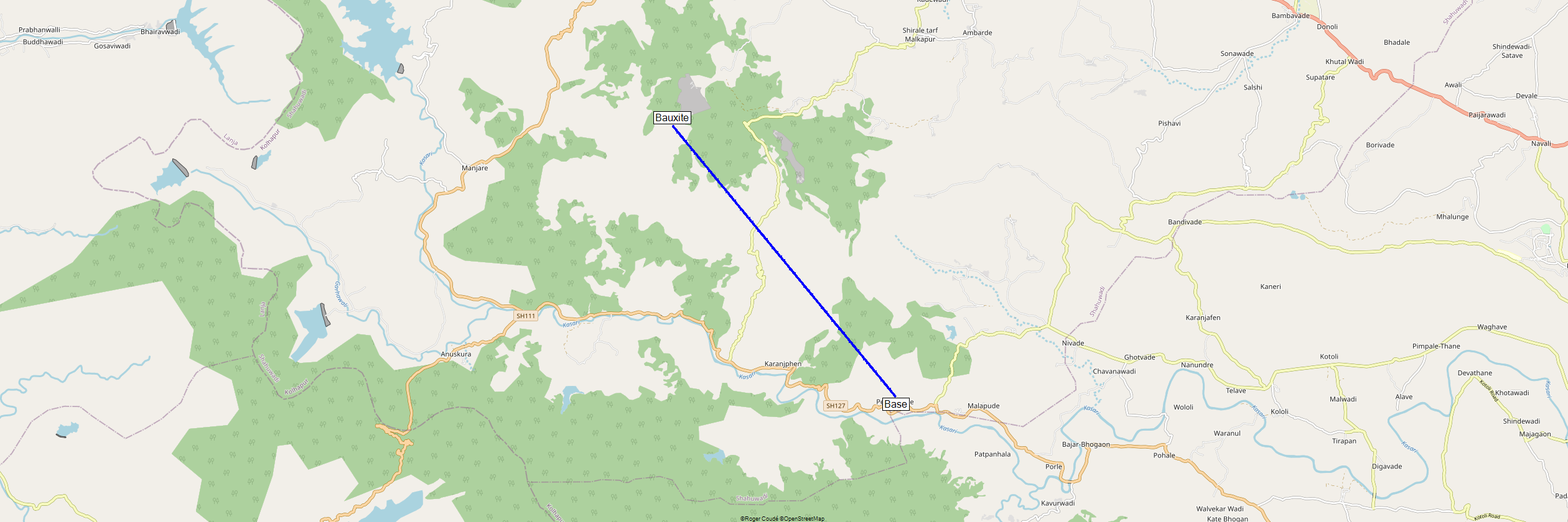
Based on the terrain data from Google Earth, Pendakhale, the location of our base camp sits at an altitude of roughly 580 meters. On the other hand, the Bauxite mine at Girgaon sits at an altitude of 950+ meters. Best communication happens when there’s what we call as “Line of Sight”. Now, line of sight suggests that there is absolutely no physical obstruction present if we were to draw a straight line between the two points, allowing for unimpeded visibility or communication between them.

Observing the elevation map above, we can quickly understand that the radio waves don’t have a clear line of sight. Even from the highest point, the radio waves would be obstructed by the hills near the base camp.
Assuming, we had a clear line of sight, it’s a distance of 10.6km that the radio waves needed to travel for communication to happen.
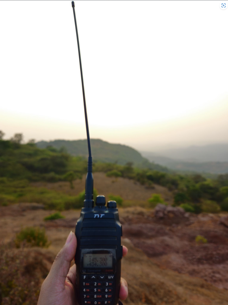
At the base camp, we had an FT2980R base station transceiver which we had set to low power. A low power mode equals 5W of transmit power. Similarly, the bauxite mine repeater was set to transmit 5W of power. Furthermore, during the testing, I had a TYT UV8000E handheld transceiver which was also set to low power (1W Tx Power).
Friis transmission equation
For clear communication to take place, it’s imperative that the received signal power is well above the receiver noise floor. Any signal which goes below the noise floor is impossible to read clearly. For any signal to be readable, it must be at least 10dB above the noise floor in case of voice communication. In other words, for a readable communication, a 10dB signal-to-noise ratio (SNR) is needed.
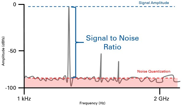
So far, we have a few parameters at hand that are needed to understand what we call as the Friis transmission equation. This equation is widely used to calculate the power of the signal received at the receiver after it travels through free space.
\(\scaleto{P_r = \frac{P_{t}G_{t}G_{r}{\lambda} ^2}{4\pi R^2}}{25pt}\)
Here, Pt = 1W, Gt = 1.5dBi, Gr = 6dBi
We used the VHF band for testing which has a wavelength of 2 meters. Therefore, \(\lambda = 2m\). Measuring the point-to-point distance between the two communication points, we arrive at R = 10.6 km.
When we put all these parameters in the above equation, we get a received power of 1.35nW (nano Watts). A huge loss of power indeed!
Converting this power into log scale, 1.35nW equals -58dBm.
Our receiver at the base camp has a sensitivity of -114dBm. Our received signal is 56dB above the margin. This will result in 5/9 communication. Let’s not forget, that this is still an ideal scenario where we have not considered vegetation, mountains, moisture, etc.
Back to geography
Looking back at the first, if we drew a straight line from the bauxite station to the base camp, we were obstructed by a large hill close to the base camp. The Friis equation alone would not hold. We need something more elaborate. It is where we learn about a new concept called knife edge diffraction.
In short, when radio waves hit an edge, it bends and goes all over the place.
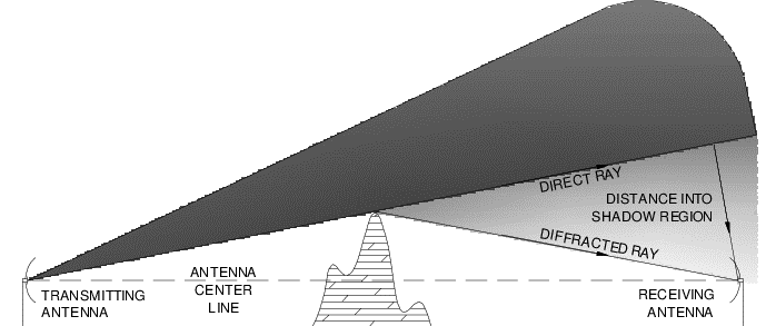
Interestingly, in the above figure, we see how the transmitted wave, although obstructed by the mountain, still manages to reach the receiving antenna. The radio waves diffract and spread across a wider area.
A similar case occurs in our communication. The large mountains are responsible for the diffraction which results in radio waves reaching our destination.

The above figure shows the cross-section topography map of the aerial path between the bauxite station and base camp. A straight line from the bauxite mine to the base camp gets obstructed by a large mountain. On the contrary, the mountain tops are responsible for knife edge diffraction that guides the radio waves to the destination making the communication possible.
The knife edge diffraction math is a bit much to calculate manually. Therefore, I have used a tool known as RadioMobile which takes the terrain into consideration and theoretically calculates the received power at the receiver.
Additionally, apart from the topography, RadioMobile also takes into consideration the vegetation, soil type, soil conductivity, moisture, etc. The tool itself is based on the Irregular Terrain Model (ITM) which was created for VHF and UHF terrestrial broadcast coverage analysis.
Based on the output, we can evaluate if a certain communication link is feasible or not.
So, I fed all the necessary information about our setup into the tool and generated a report for the VHF link.
| Bauxite | (1) |
| Latitude (°) | 16.8424940744895 |
| Lontitude (°) | 73.8697458220901 |
| Elevation (m) | 952.9 |
| Antenna height (m) | 2 |
| Antenna type | Omni |
| Antenna azimuth (°) | 0 |
| Antenna tilt (°) | 0 |
| Beam azimuth (°) | 140.5963 |
| Beam tilt (°) | -2.1701 |
| Base | (2) |
| Latitude (°) | 16.7706669124099 |
| Lontitude (°) | 73.9313664957008 |
| Elevation (m) | 566.3 |
| Antenna height (m) | 5 |
| Antenna type | Omni |
| Antenna azimuth (°) | 0 |
| Antenna tilt (°) | 0 |
| Beam azimuth (°) | 320.6141 |
| Beam tilt (°) | 2.0771 |
The results indicate a free space path loss of 131dB and a received power of -96dBm.
Revisiting our parameters, we have a receiver sensitivity of -114dBm. We are 18dB above the noise floor. Therefore, an 18dB Signal-to-noise ratio is going to give us a very readable signal. It’s not going to be 5/9 but definitely somewhere in 4/5 to 4/4 range.
Now, you would say this is all mathematics, did it actually work? I, along with other witnessing hams would agree that communication between the bauxite station and base camp did happen. The signal report logged was indeed 4/4 to 4/5 range. It was quite exciting to experience the fact that if done right, theory and practice complement each other. A mere 1W signal can reach across the mountain all because of phenomenon known as the knife edge diffraction.

Bro it’s very helpful to know everyone how various factors are responsible for communication.