Home brewing a simple antenna analyzer – Part 1
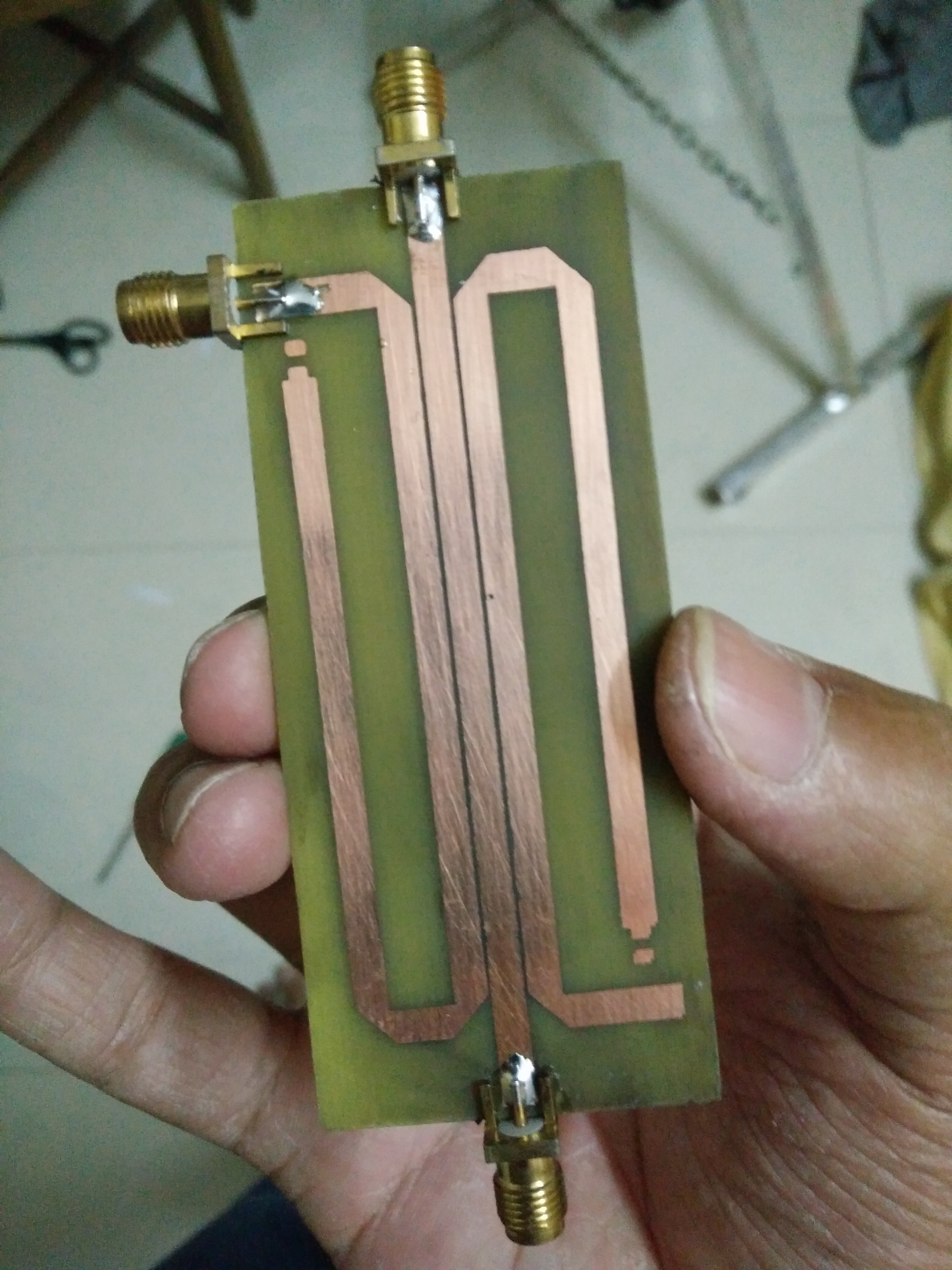
A primary tasks of an antenna analyzer is determining how good of a match an antenna has with the transmitter. One of the ways of determining that is by looking at the reflected power from the antenna port. In simple words, an unmatched impedance of the transmitter and the antenna leads to some energy being reflected back towards the transmitter. One such device capable of giving us this kind of information is the dual directional coupler.
We will be looking at a simple dual directional coupler for the VHF band amateur radio frequencies. Although the same can also find its use in the UHF band frequencies, its response changes and that needs to be taken into account.
Nevertheless, we will look at how easy it is to build a dual directional coupler which will allow us to look at the transmit as well as reflected power. Thus, enabling us to calculate the reflection coefficient and the VSWR for the antenna.
Concept
The directional coupler we are brewing follows the concept of couple transmission lines. Any transmission line has its magnetic and electric field around it whenever a signal passes through. The electromagnetic field around the transmission line induces a current in the surrounding metallic objects. The magnitude of the current depends on the frequency of the signal passing through. A higher frequency signal is bound to induce more current in surrounding objects than a low-frequency signal. Faraday’s law explains this phenomenon very well, but we are not going to go there. Another factor determining the magnitude of the induced signal is the distance at which another object lies from the main transmission line. The magnitude of induced signal is directly proportional to the distance from the main transmission line.
Simulations
By placing another transmission line in the vicinity of the main line, we get what is known a coupled transmission line. A simulation of this effect will help us understand the phenomena better than anything else. I will be using Advanced Design System to do the simulation.

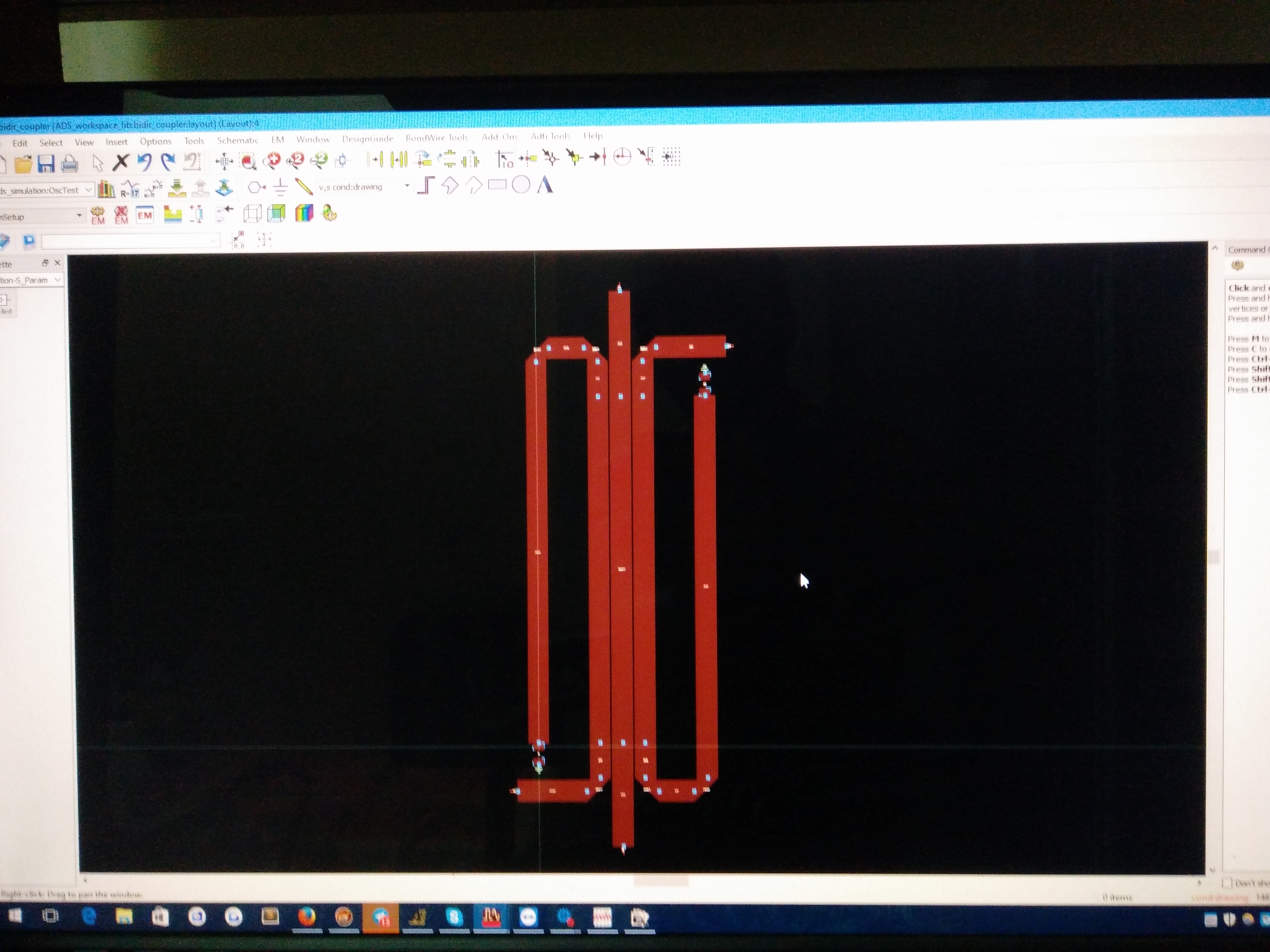
Now it is time to look at some more operational basics of the directional coupler in order to understand the simulation results.

As you see in the image above, the dual directional coupler has 4 ports. Port J1 and J2 connect to the main line whereas, port J3 gives a small percentage of energy flowing from port 1 to port 2. Similarly, port 4 gives a small percentage of energy flowing from port 2 towards port 1.
Understanding a little math
Coming back to our design, I have designed the port 3 and port 4 to provide -20dB of the forward and reflected power. To understand in terms of Watts, follow the example below.
Assume that we are transmitting 1W of power from Port 1 to Port 2. Also assume that the antenna connected to port 2 has a perfect matched. In this case, we will be able to see only 1% of the transmitted power on port 3. On the other hand, we should see 0W power on port 4 since there is no reflection because of the perfect impedance match.
In case of a small mismatch in antenna impedance, there will be some power coming in the reverse direction. That is due to the reflections occurring at the interface of mismatch. We can see 1% of whatever power coming in the reverse direction. Power will reflect backwards in cases for example, say we have a 75 Ohms antenna connected to our 50 Ohm directional coupler. This mismatch will result in a return loss of -13.9 dB (equivalent to 4%). In other words, 4% of the transmitted power will return back. Now, the port 4 will show 1% of the reflected power.
Again keeping the above assumptions, we will see 40mW at the port 4.
The simulation results
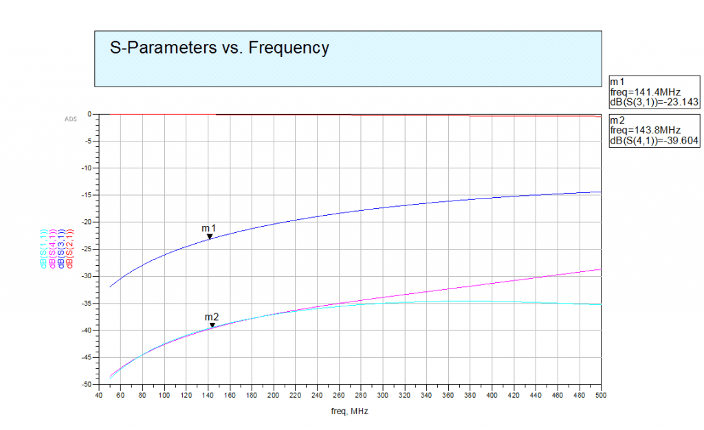
You will need some understanding of the S-parameters in order to interpret the results shown above by yourself. Nonetheless, let us simply understand what it means for us.
The marker M1placed on the trace S31 tells us the percentage of forward power coupled into the port 3. Similarly, the M2 marker gives us information about the power in the port 4 even when there is no reflection happening. We need to understand that the results will never be perfect. We see -39dB (1%) power leaked into the port 4 even when there is absolutely no reflection happening at port 2.
On the other hand, we can see -23dB (20%) of forward power being coupled to port 3. The coupled power increases greatly at higher frequencies. I am not bothered by that because I am more interested in the 144 MHz to 146 MHz band than anything else.
The Real results
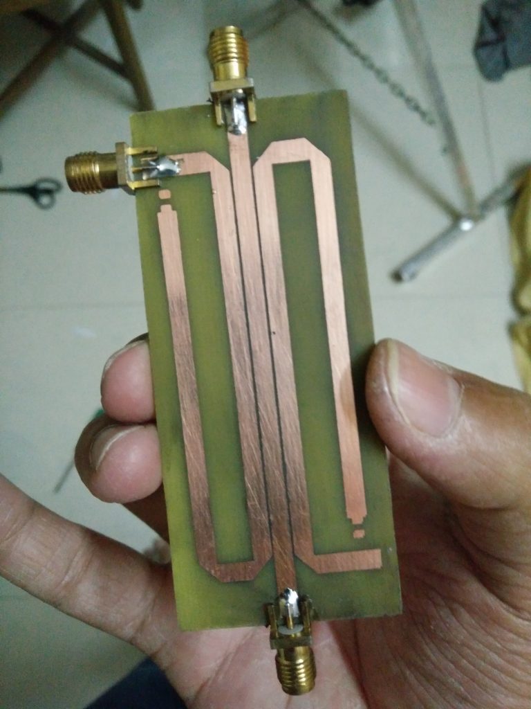
After fabricating the dual directional coupler on a PCB, we have something which looks like this.
Now we hook it up to a couple of instruments for analysing the response on this little thing. I will be using SignalHound Tracking generator and a Spectrum analyser to analyse the response of the main transmission line. This is done in order to determine how much insertion loss it offers across the band.
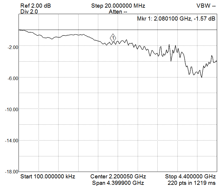
The S21 measurement shown above gives us a clear picture of how much insertion loss it it has across the 100kHz to 6GHz bandwidth. Looking closer we can see the loss becomes pretty bad at higher frequencies. It appears that this little coupler can work all the way up to 3GHz at least. A -6dB loss at the higher end of the spectrum is not really acceptable. Since, the instruments I am using are not that accurate for measurements in that range, we should simply ignore the higher frequencies.
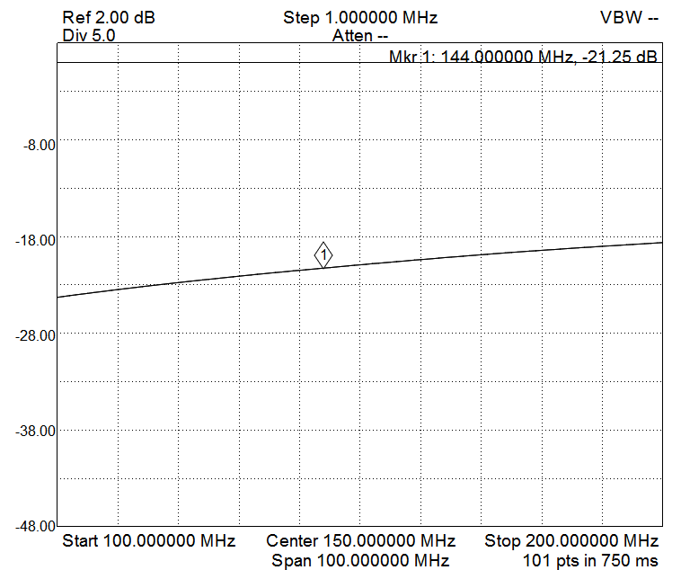
The port 3 of the dual directional coupler should give us a coupling of -23dB according to the simulations we did earlier. Looking at the image above, it appears that we are getting -21dB coupling. This is really as close as we can get to the simulations. All in all, I am pretty happy with the results. The port 4 on the other hand gives an astounding -43dB isolation. That again is as close as you can get to the simulated results.
Given the fact that port 2 and port 4 will have an identical response, I feel no need to upload the results for those here.
Finally, I can say that this little home made dual directional coupler will find use in a couple of larger home brew projects. One of it is going to be an FMCW radar that I am working on.

Hi. Very interested in your design… but can not find part 2 of your article.
Do you have any further info… particularly the PCB design detail. I am not even sure if it is double-sided… and how it is mounted (spacing etc.) in a housing. Many thanks.
Do you sell those boards? If so is there a parts list for that as well? and if there is a parts list, is there a kit of parts?