How To Install An Alarm System – Paradox SP5500
Security has always been a major factor in our lives. Ever since prehistoric times, the man wanted to protect his territory from other men that had evil intentions such as stealing or trying to commit murder.
At the present time, technology has advanced so much it had a constant change in the security department.
We have more advanced surveillance systems and alarm systems and the chips are more intelligent.
Although not everyone was ready or planning to buy these security solutions. People have not installed these high tech security solutions as a preventive measure before the unhappy event even happened.
Despite their stubbornness, since there has been an increasing number of thieves lately, therefore lots of people changed their minds and started searching for a solution to protect their business, their home, their land.
For the purpose of preventing burglars from going in, people install surveillance cameras to supervise the surroundings but sometimes that is not enough to prevent thieves from barging in.
This is why alarm systems are so important. Once the user installs an alarm system, the sensors detect any moving target, using heat detection, then proceeds to start the siren and send an SMS message to the owners so they know their house has been robbed.
Without further ado, let’s head on to explaining how we install an alarm system ourselves in case of inability to cooperate with a security company.
IMPORTANT! Recommended to install an alarm system with a security company because they offer important papers that are given to and by the police.
In case of a robbery, police is the authority that inspects the surroundings in order to catch the thief.
This guide consists of several steps a user needs to take in order to install a security alarm system:
- List of compulsory hardware and software parts to install/buy for a Paradox Sp5500 alarm system;
- Component description;
List of compulsory hardware and software parts to install/buy:
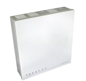
Central Box with the transformer in it;
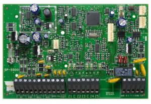
Sp5500 Board;
Wired Sensors;
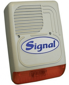
Wired Siren;
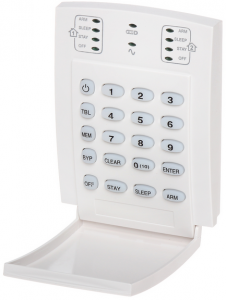
Wired Keypad;
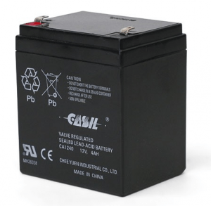
2 Batteries 4Ah (7Ah) 12V DC;
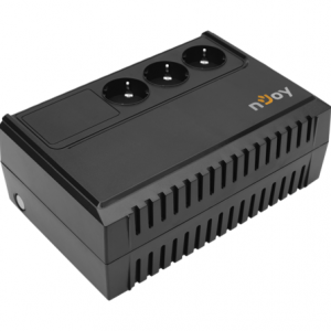
AVR or UPS;
A laptop with Babyware software installed;
Insulation tape;
Alarm cable with 4 wires respectively 6 wires for Siren;
Drill power tool;
Cordless Screwdriver Tool
Screwdriver;
Screws and wall dowels;
OPTIONAL for installment:
RTX 1 or RTX 3 modules for wireless signal transmission;
PCS (GSM transmitter)
Remote REM 15 or REM 1 for remote signal transmission to ARM , DISARM , PANIC
Wireless sensors , magnets, keypads, sirens
IP 150 Module (requires a router and Internet and special cables)
Component description
CENTRAL BOX WITH TRANSFORMER
Usually, there has to be a metal box for each and every alarm system panel. It allows being pinned still to the walls, so the wiring process can occur or it can rest batteries inside including a transformer.
The transformer works with 220V Alternative curent and gives DC curent in exchange to power up the panel.
In detail, batteries act as a backup for the panel in case a burglar comes and kills the power supply everywhere in order to get inside.
More than often, batteries last about 7 – 8 hours before they deplete and hence the panel stops recognizing that it has any battery power left.
SP5500
It is mainly the brain of the alarm system. Sends signals everywhere and receives from everywhere. Opens and closes zones. Fry that one and the whole system falls with it.
SP5500 by Paradox has the following description:
| Features | SP5500 |
| StayD | |
| Maximum Zones | 32* |
| On-board Zones | 5 (10 with ATZ) |
| Expansion Zones | 24 |
| Keypad Zones | 15 |
| Partitions | 2 |
| User Codes | 32 |
| PGMs | 16* (2 on-board) |
| PGM +/- Trigger | – |
| Alarm Relay | – |
| Event Buffer | 256 |
| Wireless Expansion (RTX3) | Yes |
| Wireless expansion (RX1) | Yes |
| 2-Wire Smoke Detector Input | – |
| GPRS / GSM Module (PCS Series) | Yes |
| Compatible with IP100 | Yes |
| Compatible with VDMP3 | Yes |
| Patented 2 opto coupler dialer circuit (US Patents 5751803, RE39406) | Yes |
| In-field Firmware Upgradeable | Yes |
Wired sensors
Wired sensors are an important component within an alarm system. They detect heat signatures within their beam range and sends signals directly to the control panel to trigger the alarm. To wire them, a cable of 4 wires is required.
There are many types of sensors but notably, the ones that are most useful are NV5 and 476 motion detectors.
NV5
It’s easy to install. Furthermore, can clip the board in and out easily.
Strong points:
- It is a digital motion sensor.
- Wiring is also not complicated at all.
- Requires basic knowledge.
- Pet immunity included.
Beam pattern:

476
One of the most awesome sensors out there for Paradox alarm systems.
Strong points:
- It is an analog type motion sensor. Flawlessly detect in milliseconds.
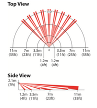
- The working range is far (11m) and the beam pattern is extreme (around 110degrees).
- Extremely high EMI and RFI rejection.
Beam pattern:
There is a joke going around about 476 seeing the target even behind a corner.
Wired Siren
Often, almost every alarm system uses a siren, unless the owner wants to surprise the burglar. In this case, he won’t install the siren.
Wiring is simple, requires basic knowledge. A special alarm cable with 6 wires is required.
The user must install the required backup battery in order for the system to function.
PS128 Signal siren:
| Features | PS128 |
| Sound output | High, loudspeaker |
| Siren type | 7 types |
| Sound pressure | 128 dB |
| Tamper protect | Tamper switch |
| LED display | Life signal |
| Inputs | Flash, Service, Start 1, Start 2 |
| Outputs | Report, Tamper |
| Self-test every 6 or 24 hours | Yes |
| Dimensions | 295 x 200 x 100mm |
| Maximum battery size | (12V), 4Ah, 7Ah |
| Housing | Double (ABS + steel) Vandal Proof |
| Mounting | Onto Wall |
| External / Internal | External |
| Protection level | IP34 |
| Weight | 3000g |
| Power supply | 13,8V DC |
| Curent consumption | 25 mA |
Wired Keypad
Wired keypads are used to input codes of arming disarming. Mounted within the space that needs to be protected. There are several types of keypads K636, K10V, etc for Paradox.
Strong points:
- Easy to mount on the walls.
- Wiring is also easy,
- It requires basic knowledge.
K636 Keypad
| Features K636 |
| Compatible with MG5000, Spectra SP series |
| Single partition keypad |
| 10-Zone LED display |
| StayD status LED |
| Arm, Sleep, Stay and Off keys illumination to indicate partition status |
| Adjustable backlight |
K10V Keypad
| Features K10V |
| Compatible with MG5000, MG5050, Spectra SP series |
| Supports StayD Mode |
| 10-Zone LED display |
| Separate Arm, Sleep, Stay and Off LEDs per partition |
| 1 Keypad zone input |
| Independently set chime zones |
| 7 one-touch action buttons |
| 3 keypad- activated panic alarms |
| Adjustable backlight |
| Connects to a 4-wire communication bus |
Batteries
Batteries are a very important component of an alarm system. Without them, the alarm system wouldn’t start.
For instance, backup batteries are able to continue powering up the system for 7 to 8 hours after the main power supply has been cut off. Both the Siren and the Main control panel use 4Ah or 7Ah (12V DC) batteries in order to work.
Be wary though, the lifespan of such batteries is only ~ 2 years.
AVR or UPS
An AVR (Automatic Voltage Regulator) is useful in situations where there is trouble with the main power supply eg. Power outages, shortages, spikes. Additionally, regulates the curent so it gives a constant 220V without fail.
Power issues
Unless the power spikes are too great, in which case the devices will break, but most of the times they stop the excess of voltage. AVR is useful for just about any electrical device, to be honest, even PC’s, TV etc.
A UPS (uninterruptible power supply) uses a separate power backup in case the main power source goes off. It also has an automatic voltage regulator included.
Price can vary between AVR and UPS because the UPS has more features than the simple AVR.
Recommended: UPS that can last about an hour after the power has been cut off.
OPTIONAL COMPONENTS
- RTX 1 or RTX 3 modules for wireless signal transmission;
- PCS (GSM transmitter)
- Remote REM 15 or REM 1 for remote signal transmission to ARM, DISARM, PANIC
- Wireless sensors, magnets, keypads, sirens
- IP 150 Module (requires a router and Internet and special cables)
RTX 3
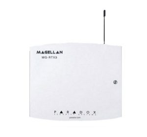
RTX 3 module is used to extend wireless signal to SP5500 series in order to use REM 1 or REM 15 remote control or install wireless components such as wireless sirens, wireless sensors, wireless door magnets etc.
It has a simple wiring process and it’s also easy to mount on the wall.
PCS
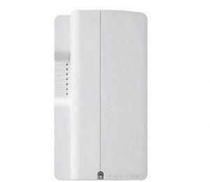
PCS (GSM) signal transmitters help the user by sending Text messages through SIM technology network. In other words, it acts as a mobile phone.
Every time there is an arming, disarming, alarm process, the module proceeds by sending the text message to the user, hence informing him about the possible break-ins or troubleshooting that needs to be solved.
Features of PCS 250G used for Paradox Alarm System:
| Features PCS 250G |
| 4G (3.75G) reporting the speed of system data to IPR512 Monitoring Receiver or IPRS-7 IP/GPRS |
| 3G /2G auto connect if 4G is not available |
| Two SIM cards support for provider redundancy |
| Control panel communication supervision |
| Future-ready for smartphone application access |
| Arm or disarm the system via text message to the PCS |
| Special cable used to connect to the control panel |
| Dual tamper switch (wall and cover removal) |
| Encrypted communication (128-bit) |
Remote REM 15
Remotes are used as a means of comfort to send Arm, Disarm, Panic signals to the control panel to trigger the commands. RTX 3 (or RX 1) is required to be installed in order for the signal exchange to happen.
Wireless motion detectors
Wireless motion detectors work in the same way as any other wireless alarm system component. It sends and receives signals in order to trigger a command or an alarm. A most notable motion detector that proved to be useful is PMD2P that is used for SP and MG series.
Strong points:
- The wireless solution is the most useful when there is no way to use wired motion detectors.
- It’s easy to install anywhere in the user’s house.
- Batteries last for about 2 years.
Beam pattern:

Features of PMD2P Motion detector are as following:
| Features PMD2P |
| Dual element sensor |
| Immune to animals weighing up to 18kg (40lb) |
| 11m x 11m and up to 15m for center beams with 88.5 degrees viewing angle |
| Wireless range in a typical residential environment:
-70m with RTX3 |
| Automatic temperature compensation |
| 3-minute energy save mode after two detections within a five minute period |
| Dual tamper mechanism (wall/cover) |
| Slide switch to select a high or low sensitivity |
Wireless magnets
Wireless magnets work in the same way as any sensor, except they are used for windows and doors.
An alarm is triggered when the connection between the magnets pair gets cut off, hence sending a signal to the control panel that someone opened the door/ window while the system was armed.
Batteries last for about 2 years.
Wireless siren and keypads
These components work in the same way as any other wireless alarm system components. They are used for comfort, visual appeal if the user wants no cable to be used. Batteries last for about 2 years.
IP150 Module
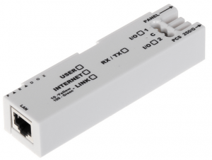
It is mainly used to connect the alarm system to the Internet in order to use certain dedicated applications such as Paradox InsiteGold. A router is required in order to receive an Ip address for the module.
Feature for IP150 Module are as follows:
| Features IP150 Module |
| HTTPS support for improving security (HyperText Transfer Protocol Secure; a widely used communications protocol for secure communication over a computer network) |
| Two I/O’s on board; controlled via the web interface, triggering an email |
| Easy installation; built-in clip for mounting in a metal box |
| Report control panel events via IP to the Paradox IPR512 GPRS/IP Monitoring Receiver |
| Control and monitor a control panel through an IP network (LAN/WAN/Internet) |
| Compatible with Spectra SP series, MG5000 / MG5050 (both requiring control panel V2.10) |
| View the live status of all zones and partitions (open/ closed, armed/disarmed, troubles, alarms in mobile app |
| Very low bandwidth consumption |
Mounting process
Generally speaking, for mounting the required components to create a full alarm system, it is required a lot of patience to get it done, including a set of tools that I will describe.
In other words, what will actually be explained in this article is how to mount the most important components that are making a full alarm system.
There is a much better explanation of the mounting process in the installation manuals that each product get individually in their packages or boxes.
Here we go.
- Make sure all the cables for the alarm system have been centralized to where the main metal box for alarm system will be present. The other ends of the cables must be for each individual sensor and other components that require wiring.
If the house has already interior fully painted and ready to live in, to avoid creating unnecessary wall holes we suggest using a wireless alarm system.
To finish the cable process, write on each respective cable where it leads to, in order to avoid confusion during the wiring process.
- Prepare the metal box that will hold the board, battery, and other components.
- Make sure the metal box is near a fuse panel so when there is time to get electricity, we can just wire a 3×2,5 electricity cable with one of the fuses.
Preferably it must be a C10 fuse because the alarm system is not power hungry.
- Check from where the cables start to centralize. Place the metal box where the most cables are at to hide them eventually.
- Place the metal box (make sure to already pin the SP5500 board inside), use a screw to mark on the wall 4 points to each corner of the metal box.
- Drill 4 holes, insert 4 dowels, put the metal box back on the wall, use a cordless screwdriver to pin 4 screws into the box to the wall.
- Proceed the same with the sensors and keypads. For the siren, it might be necessary the use of different types of dowels.
- The other optional modules (such as RTX 3 or pcs250g) might not require pinning to the wall if there is enough space inside the box after the wiring process has been completed.
Wiring process
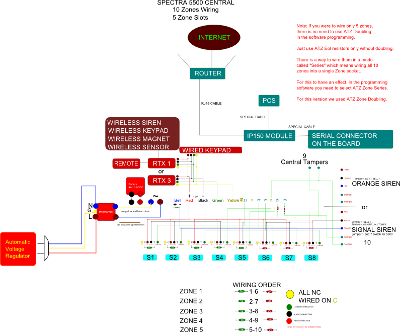
To help better understand this process, we have created a scheme to explain how the wiring is done. We recommend you do not power on the alarm system during this step.
Do not forget also to remove the fuse inside the metal box near the transformer.
Or get the PDF VERSION
This wiring is from a SP4000 board
And this one is from a SP5500
For the wireless equipment, it is required to manually input the serials from each device into Babyware programming process.
System startup and programming
Once everything has been wired accordingly, proceed with starting up the equipment in the following order:
- System needs to be wired to a power source;
- Wire the battery to the siren;
- Connect the battery to the SP5500 board;
- Insert the fuse near the transformer back in;
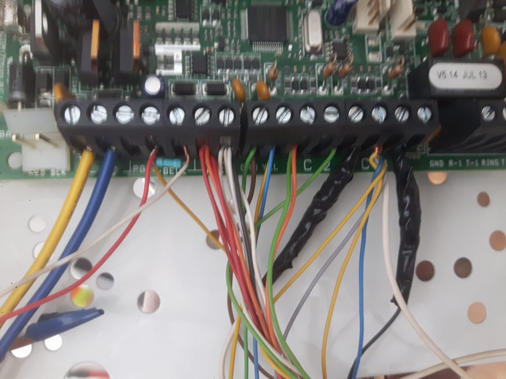
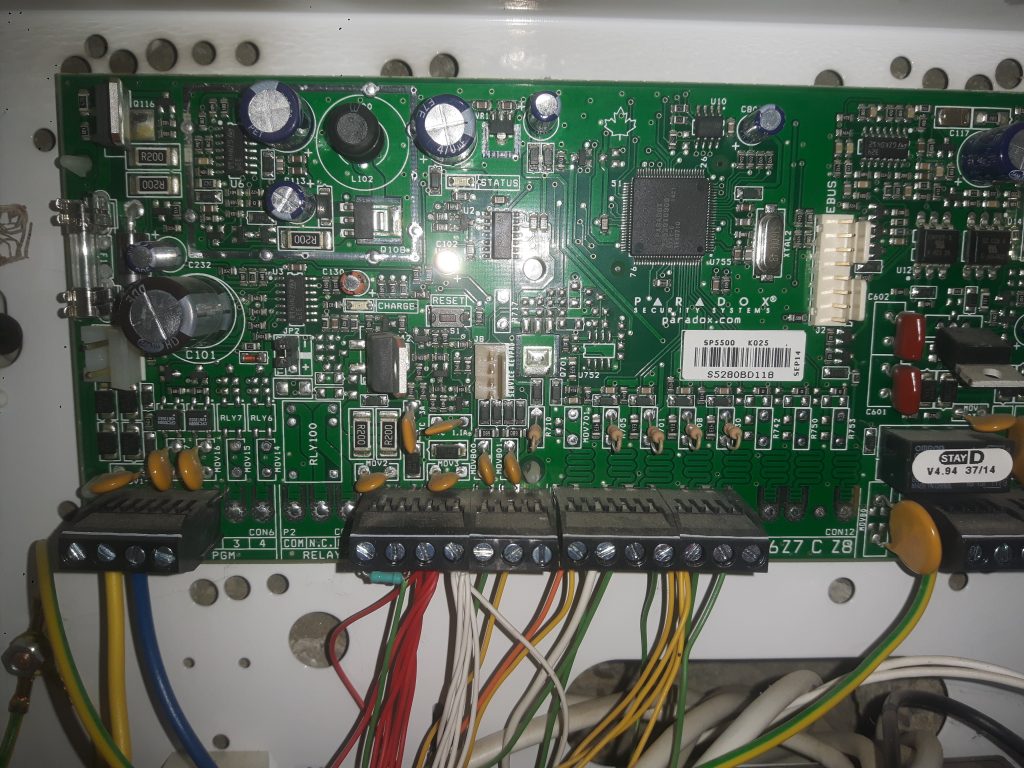
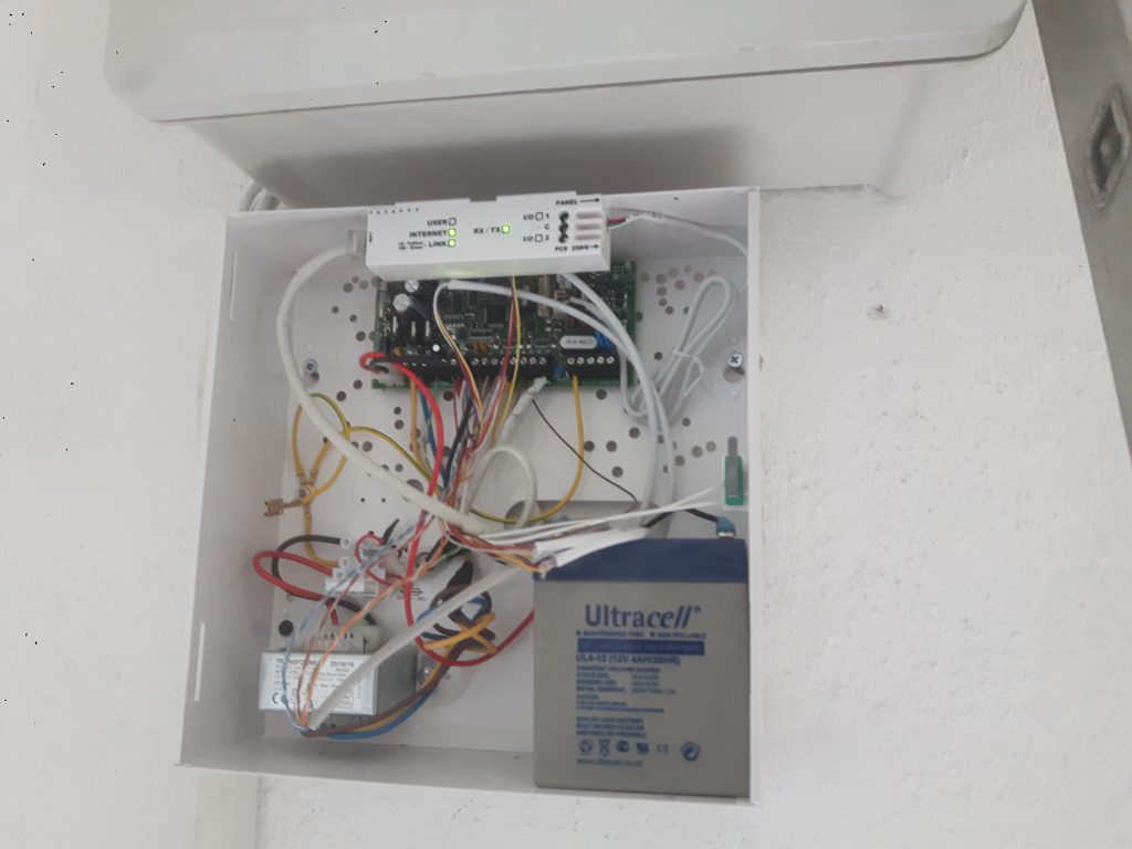
The final version should look like this:
Babyware software
There are many tutorials on how to use babyware software, so I won’t cover everything from A to Z.
Here are some of the steps:
- Start Babyware program;
- Create a user; connect via serial;
- Select Zones; check AOL resistors and Parallel zones;
- Enable each sensor as you wired them according to the scheme presented at point 4. For siren and metal box tamper use 24h panic. Use the entrance sensor as Entry Delay 1.
- Select Area; set entry delay 1 to 15 seconds (usually that much is required to input the code after entered house);
- Don’t forget to send requests by clicking the SEND button located at top of babyware’s software for every step that I described.
For PCS 250G, search for reporting / SMS messages and insert phone numbers.
For IP150 module
- install IP Exploring Tools ;
- register it on paradox MyHome;
- open ports on the router;
- bind the device mac to the router DHCP address;
- download Paradox Insite Gold from Google Play store;
- register an account to create a site ID,
- insert Panel serial located in babyware software while connecting serial in order to finish.
More of this can be found in the installation guide found in the box.
These are all the steps required to successfully install an alarm system. Especially important! Don’t forget to test the alarm system to see if it works.
If not, review the wiring process, and the settings in babyware, check for troubleshooting, call support, read the manuals for each product that might cause problems.
Keep in touch! Don’t forget to comment if you have any questions.






Hi,
How to remove and replace batteries inside the wired keypad?
Hello Roger! As far as I know, only wireless keypads eg. K37 Wireless Keypad have battery slots (Here is how you can change batteries if you have that model). K636, K10 can only be powered by direct wiring to the main central box.
The wires used are Red (+), Black (-), Green, Yellow.
Usually, wireless keypads allow powering through both ways: using batteries and direct wiring. Thank you for feedback.
Hi,
I need to reset my IP module as I gave it a invalid static IP address. I’ve been told to disconnect the battery and fuse. Is the fuse I need to disconnect on the left side of the board?
Thanks
What kind of IP module is it?
The fuse is the one on the left side that lies between the 220V wires that powers up the transformer. But before unplugging the fuse, make sure you disconnect batteries from siren and main box first. Then, reset the IP module, plug in siren’s battery, plug in main box battery and then the fuse (in the order i typed) and it should work.
If it’s IP150 module for Paradox, have you tried using their Insite Gold service? I use that for all my clients and they don’t mind paying 12 euros per year. It’s very effective. Do let me know abot the model of IP module, i’m curious. Cheers!
Hi
Please an you advise how to connect an led probe on a paradox sp65 to show flicking light when arming and solid red light when armed some people use only 1 wire on the led light what is the pgm program and connection to board that i must connect to?
Thanks
Hello Ridwaan, i don’t think i have ever tried what you said. I’m afraid i can’t help with that. Nice to see people try new stuff, maybe i should do the same. May i ask what you need to check it for? I never installed SP65 but i did a quick search and it looks like any other Paradox SP product. Cheers!
How did you wired and programed metal box tamper kit? I pg. it as 24 hr burglary zone but if door is open then it is all OK, if I glose it then its generate alarm. It should be opposite way. How I can programm zone as N.C
It’s actually a great and helpful piece of information. I’m happy that you
just shared this useful information with us. Please keep us up to date like this.
Thank you for sharing.
Hi, can anyone please help ?
Have SP5500 + 7 sensors DG75+ ONLY ONE ZONE and I don’t get how to wire them.
So all blacks go to black (-) and all red (+) wire go to red. On my sensor there is NC, COM, +, – , TAMPER an TAMPER port. So, all NC goes to C. What about COM, TAMPER and TAMPER and where to put resistors if any ?
I have an SP6000 and connected a PCS250G via serial cable on both ends, this helps me monitor the system via txt msg responses but it does not accept commands through msg like arm/disarm. Any idea as to why?? Thanks.