
Quickly designing a 23cm Hairpin filter in ADS
A 23cm hairpin filter operates around the 1.296GHz amateur radio band. The frequency being low enough allows us to fabricate it on a low cost FR4 substrate. It operates as a bandpass filter. There are several technical write-ups that explain the mathematics behind this filter. I won’t be really going into that aspect in this post. For someone designing professionally should definitely follow the mathematical route. On the other hand, I would be making the design intuitively.
You should fix your operating frequency before starting the design. I plan to create the design for 1.296GHz frequency which happens to be the amateur radio frequency. You can use any EM simulation software for this. I would be showing the entire process in ADS 2019.
Like I said earlier, I intend to fabricate this filter on a FR4 substrate which normally has a dielectric constant between 3.7 and 4.7. Such a wide variation in dielectric constant would cause our design to shift in frequency. The fabricator I would be using has a FR4 substrate with 4.3 dielectric constant. Now, we have fixed most of our fabrication parameters and we should proceed with the design.
The Keysight ADS is a powerful software that provides plenty of tools related to transmission line calculation and so on. I will use those tools to compute the transmission line impedances and so on.
Let’s create a basic hairpin filter structure in ADS schematic.
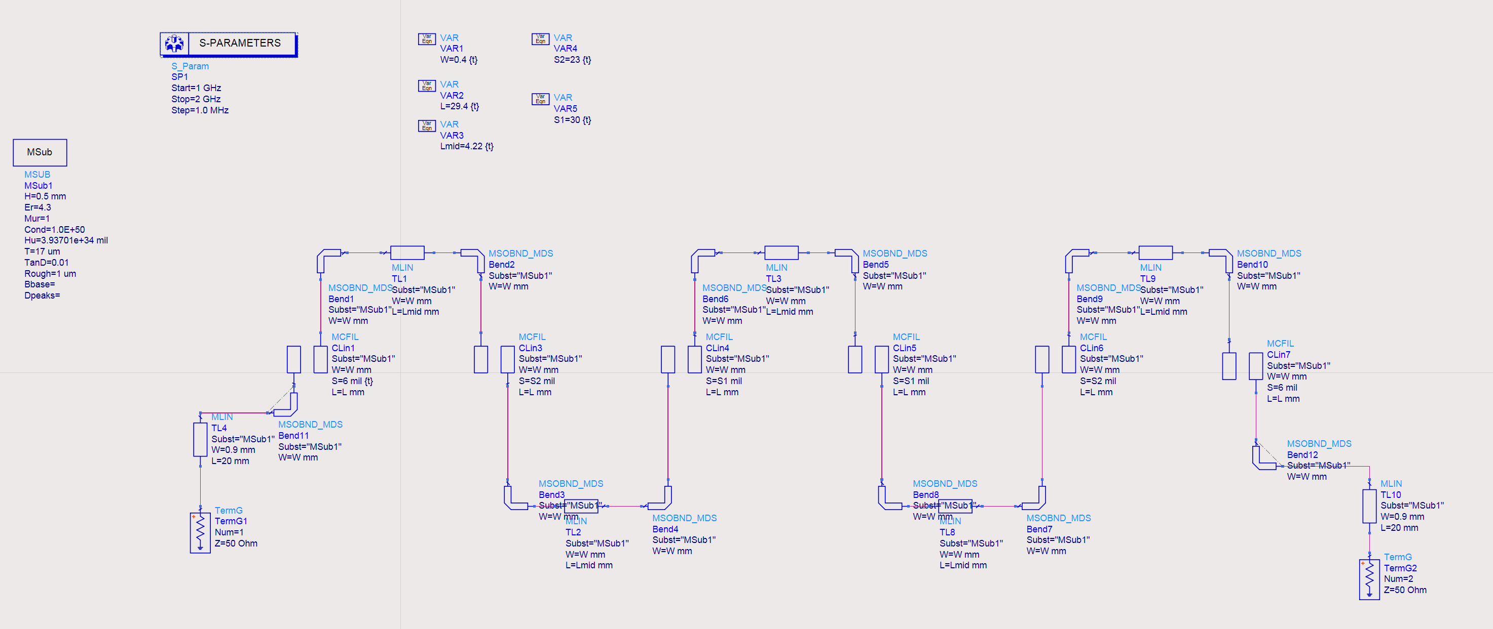
ADS Schematic for 23cm hairpin filter
The TLines library in ADS consists of all the commonly used transmission line structures. For example, the straight microstrip line, microstrip bends, open or short microstrips, etc. Before we use any of the microstrip components, we must place a microstrip substrate block that defines the substrate properties.
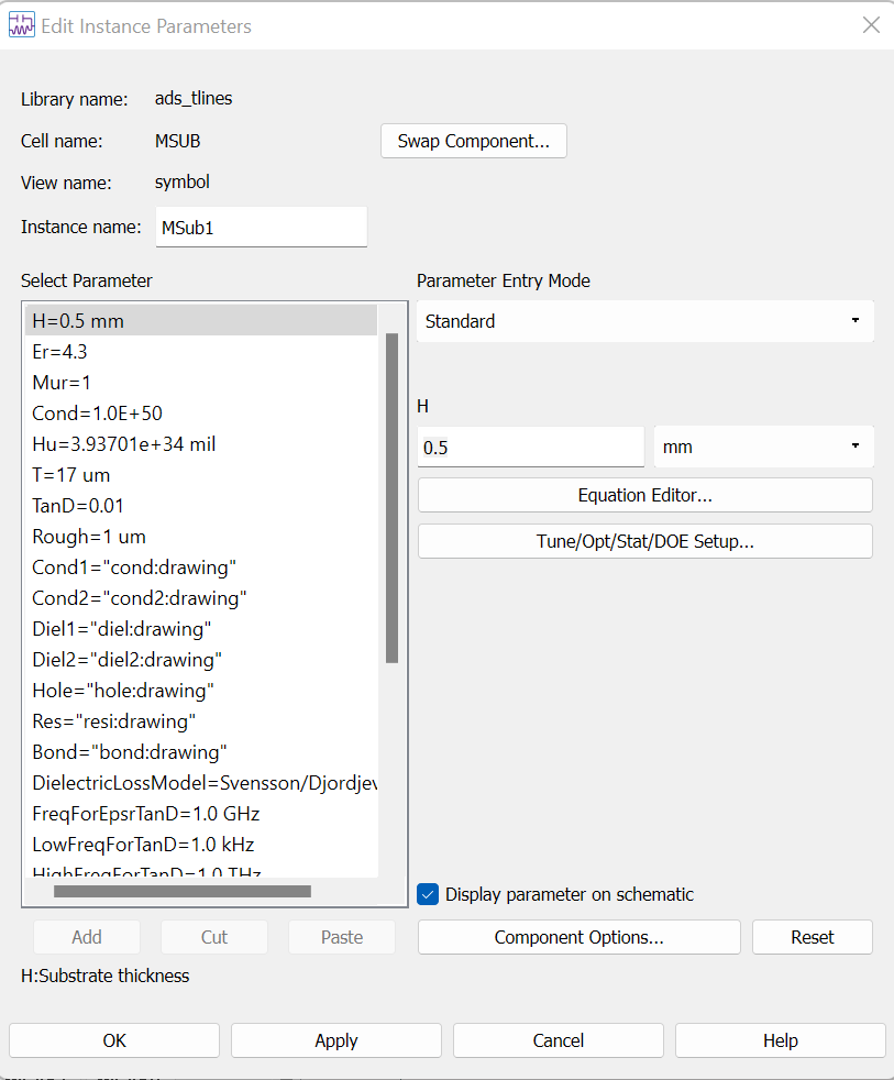
I chose the FR4 substrate with 0.5mm thickness. Rest of the parameters come from the PCB manufacturer. You should also contact your fabricator to get the exact substrate properties to ensure a good design. Otherwise, a different substrate may cause your filter to drift to a different frequency.
I ensured that the feedline impedance stays 50 ohms at both, input as well as output. Further, I also used microstrip bend component wherever there are bends. To achieve an accurate simulation result, we must represent all the connections correctly. A missing microstrip bend or a mid-section strip will easily shift the frequency response of the filter.
To make things simpler, I defined variables for the microstrip widths, spacing between coupled lines, length of the lines, etc. The first and the last coupled lines have an identical spacing. Moving inwards, the second and the second to last coupled line sections have identical spacing and so on. If you look carefully, the spacing across the filter structure is symmetric.
| S1 | S2 | S3 | S4 | S5 | S6 |
| 6 | 23 | 30 | 30 | 23 | 6 |
The connecting sections have an identical length of 4.22mm for all hairpins. Any change in the length of this section causes the length of hairpin to increase which results in a reduction of the resonance frequency.
The length of each hairpin arm comes nearly to a quarter wavelength of the desired frequency.
Tuning the variables
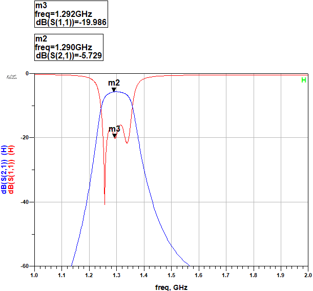
I used the tuning option in ADS to quickly modify spacings and lengths to carefully bring the filter to resonate at desired frequency. Correspondingly, we can see the S21 and S11 plots below.
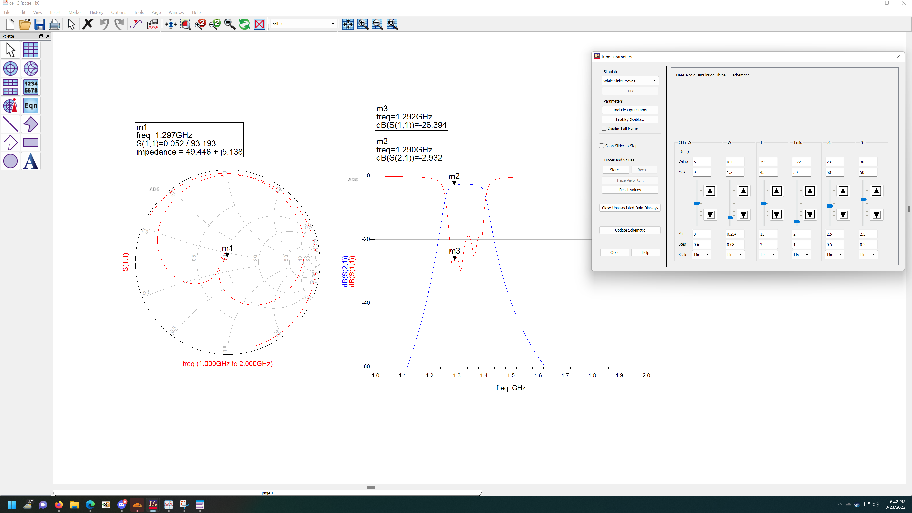
A return loss of 20dB and a 3dB insertion loss seems to be the best I could get. Perhaps, a different, lower loss substrate reduces the insertion loss and improves the overall filter response. On the contrary, FR4 substrate results in more loss at higher frequencies. So far, the results appear acceptable, and we are ready to proceed for creating the layout.
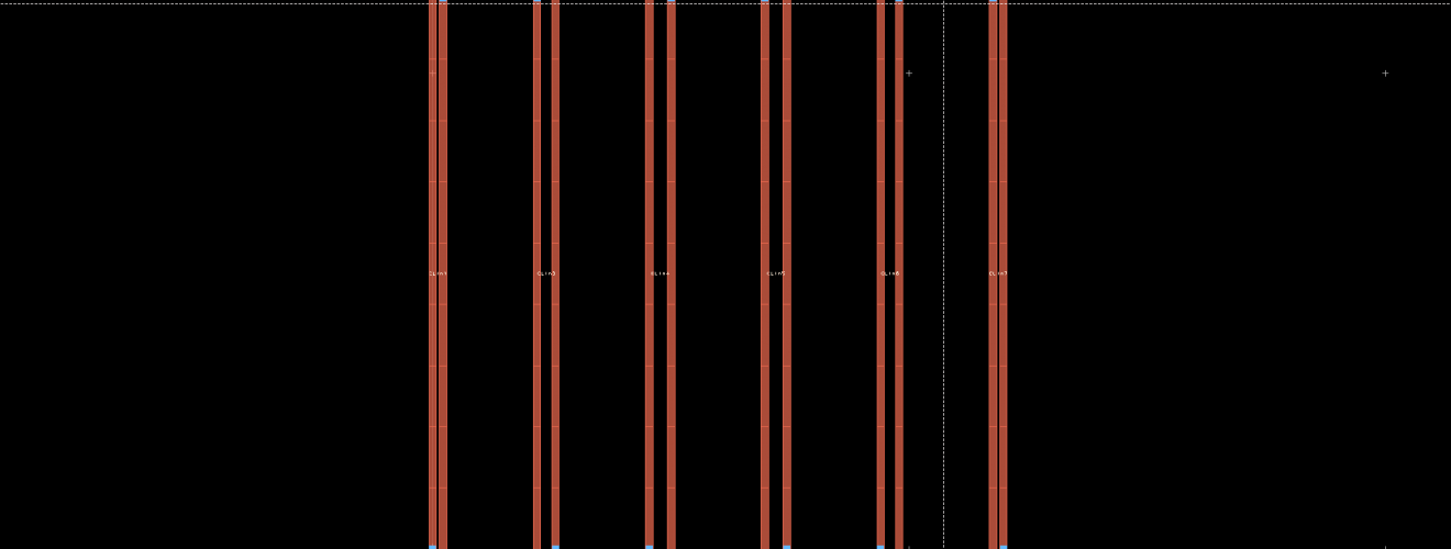
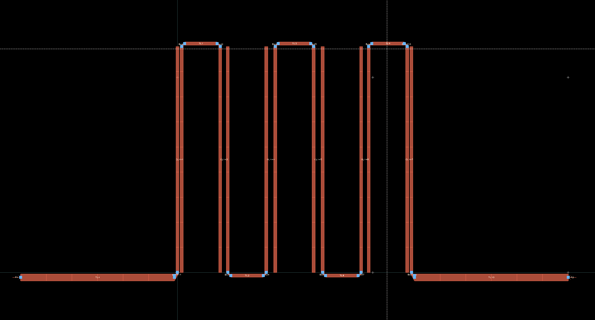
The layout of 23cm hairpin filter
We can convert the schematic directly to a layout by doing this.
Layout > Generate/Update Layout.
Doing so, automatically takes your schematic parameters and generates a layout file as follows. If you have correctly added all the microstrip components and connected them properly, you would not need to make any changes to the design.
Once in the layout mode, go to EM settings and add a new substrate. Make sure you define the substrate correctly. This will be useful while performing the layout simulation.
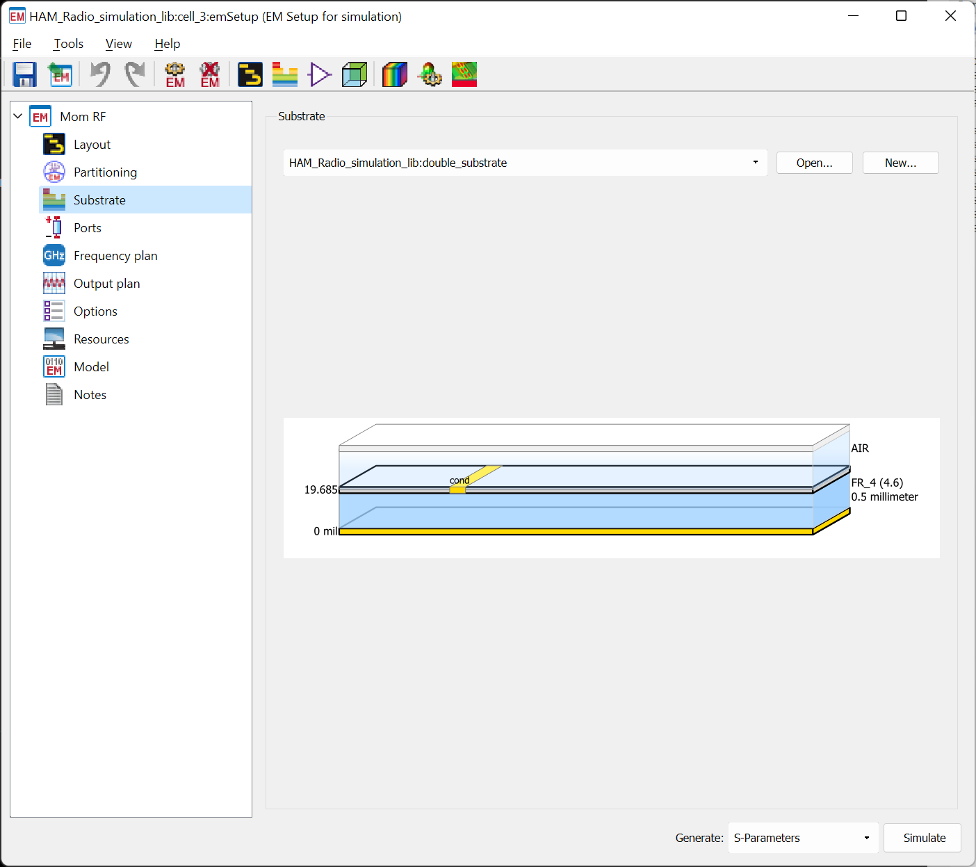
Furthermore, add two pins to the input and output microstrip lines by going here: Insert > Pin
Additionally, set the frequency plan to simulate from 1GHz to 2GHz. You should find the option in the same EM settings window. The frequency plan determines the start and stop frequency for your simulation. It also asks you the number of points between the start and stop frequency. A higher number of points will take longer time to simulate but also generate a higher resolution response plot. Therefore, feel free to play with the settings here.
Comparing the response from the schematic design and the layout design shows several differences. You should be able to quickly spot a higher insertion loss visible in the passband of the filter. In my experience, the ADS performs 2.5D simulation which also takes into account the radiation losses. On the other hand, we can also spot slight reduction in bandwidth. The return loss plot still hovers around -20dB in the passband of our 23cm band hairpin filter.
Physical measurements
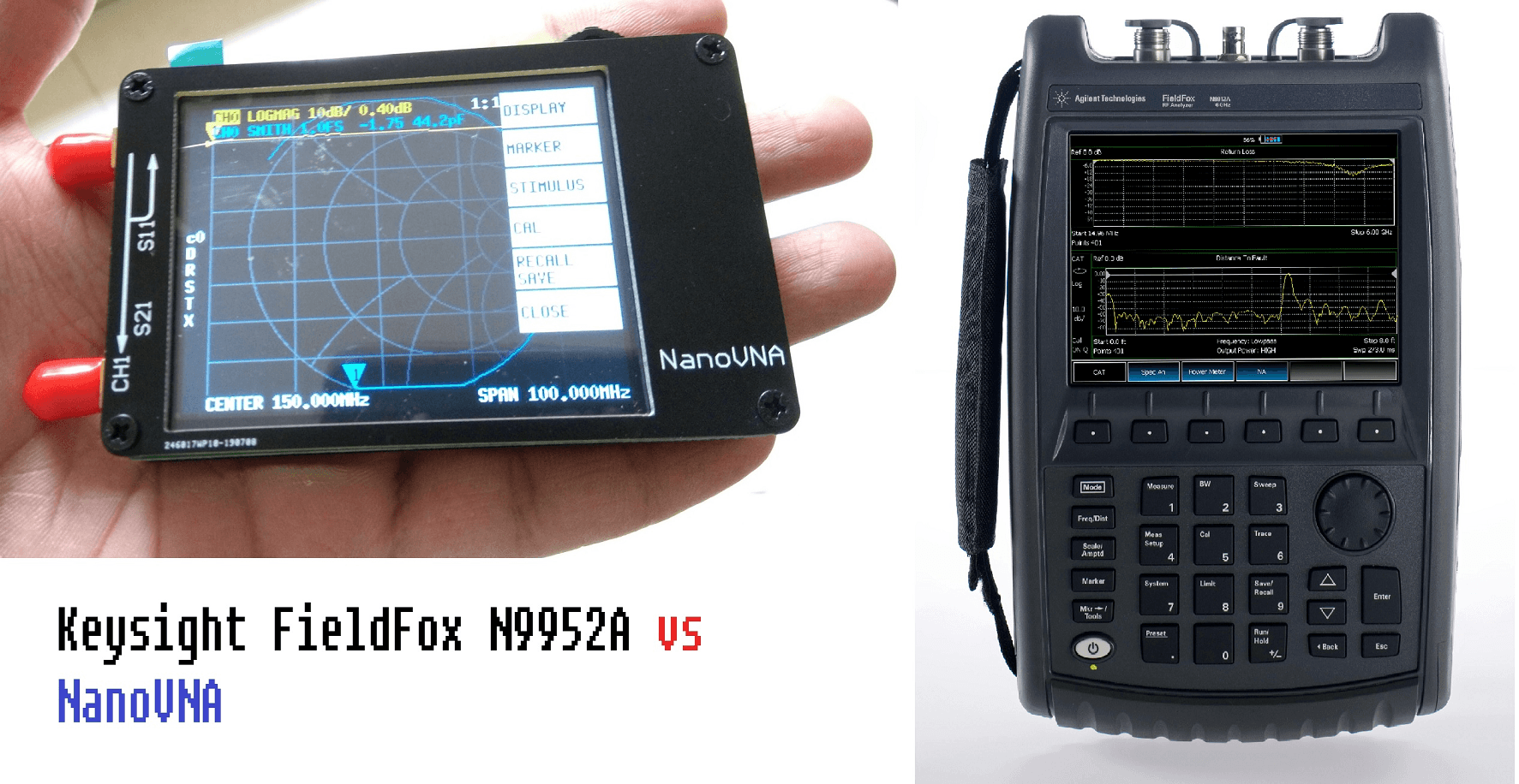
Sometime in the future, I would be fabricating this on an actual PCB and coming back with the measurements of our 23cm hairpin filter. I would most likely use the NanoVNA v2 for the measurements or the KC901 VNA. Thats all for now.

Voice of the people