
Programming the Zynq 7000 with Vivado 2019.2 and Vitis
I purchased a Zynq 7000 development board recently and wanted to play with it for quite some time now. Finally, the lock-down due to the corona virus pandemic gave me some time to put my hands on Zynq SoC development. In the past, I had spent most of my time developing RTL code for various projects. Ever since Zynq SoC had come out on the market, it had interested me mainly because of the tight integration of the programmable logic and the dual core ARM applications processor. The combination of the two has lead to integration of so many system components in various projects out there.
The best example I know in front of me is the GW Instek GDS-1102, GDS-1104 series of oscilloscopes. The entire oscilloscope has its brain embedded into a single Zynq SoC. The processing system handles the display related and user facing side of the things. On the other hand, the programmable logic interfaces with the high speed ADC and does all sort of digital processing you would expect an oscilloscope to do. If you wish to know more, head out to the EEVBlog video where Dave tears down one of the GW Instek oscilloscopes and explains everything very clearly.
Do not expect a very complicated design in this post. I have saved something good for a later date.
Block design
Consider this as a project 0 for someone who wishes to start with Vitis. A lot of projects out there related to Zynq use quite older version of Vivado and SDK. Although, most of the things remain the same, there may be a few changes here and there.
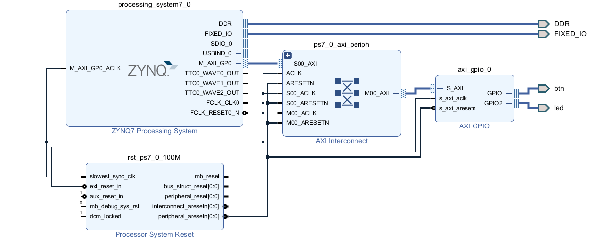
In this very simple project, I will interface 4 LEDs and 4 switches to the Zynq Processing system. The interface would be standard AXI4 because that is the only way you can interface programmable logic to the ARM processor.
It would take me ages to make a tutorial explaining every small step in the GUI. Instead, I am providing you with the tcl script that you can run and make life easy.
First, create project, select the right board and then create a new block design. Make sure you run this all in the Vivado tcl console. Also make sure you change the project according to your need.
|
1 2 3 4 |
start_gui create_project blinky J:/XilinxProjects/blinky -part xc7z010clg400-1 set_property board_part digilentinc.com:zybo:part0:2.0 [current_project] set_property target_language VHDL [current_project] |
Now, add the Zynq Processing system IP block and the AXI GPIO block. Then run the automation to connect it all together.
|
1 2 3 4 5 6 7 8 9 |
create_bd_design "blink_1" update_compile_order -fileset sources_1 startgroup create_bd_cell -type ip -vlnv xilinx.com:ip:processing_system7:5.5 processing_system7_0 endgroup apply_bd_automation -rule xilinx.com:bd_rule:processing_system7 -config {make_external "FIXED_IO, DDR" apply_board_preset "1" Master "Disable" Slave "Disable" } [get_bd_cells processing_system7_0] startgroup create_bd_cell -type ip -vlnv xilinx.com:ip:axi_gpio:2.0 axi_gpio_0 endgroup |
Now connect the DDR and the IO ports.
|
1 2 3 4 5 6 7 8 9 10 11 12 13 |
startgroup apply_bd_automation -rule xilinx.com:bd_rule:board -config { Board_Interface {btns_4bits ( 4 Buttons ) } Manual_Source {Auto}} [get_bd_intf_pins axi_gpio_0/GPIO] apply_bd_automation -rule xilinx.com:bd_rule:axi4 -config { Clk_master {Auto} Clk_slave {Auto} Clk_xbar {Auto} Master {/processing_system7_0/M_AXI_GP0} Slave {/axi_gpio_0/S_AXI} ddr_seg {Auto} intc_ip {New AXI Interconnect} master_apm {0}} [get_bd_intf_pins axi_gpio_0/S_AXI] endgroup regenerate_bd_layout startgroup set_property -dict [list CONFIG.C_GPIO2_WIDTH {4} CONFIG.C_IS_DUAL {1} CONFIG.C_ALL_INPUTS {0} CONFIG.C_ALL_INPUTS_2 {1} CONFIG.GPIO_BOARD_INTERFACE {leds_4bits} CONFIG.GPIO2_BOARD_INTERFACE {btns_4bits} CONFIG.C_ALL_OUTPUTS {1}] [get_bd_cells axi_gpio_0] endgroup apply_bd_automation -rule xilinx.com:bd_rule:board -config { Board_Interface {btns_4bits ( 4 Buttons ) } Manual_Source {Auto}} [get_bd_intf_pins axi_gpio_0/GPIO2] set_property name leds_4bits [get_bd_intf_ports btns_4bits] apply_bd_automation -rule xilinx.com:bd_rule:board -config { Board_Interface {btns_4bits ( 4 Buttons ) } Manual_Source {Auto}} [get_bd_intf_pins axi_gpio_0/GPIO2] |
Once you have run this, you should end up with a block diagram that looks something like the following.
The configurations
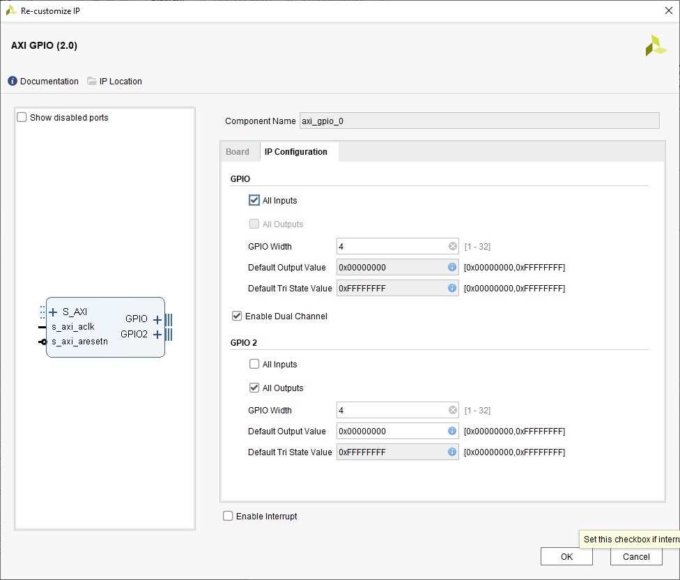
Now, we need to configure various things in the block design. If you are using one of the standard development boards, things would be quite simple. In case you are using a custom board, you will need to manually set a lot of things. In my case, I am using a Zybo Z7010 board which has 4 gpio pins set as output and 4 as input. The moment I added the AXI GPIO block, it automatically assigned it to those pins.
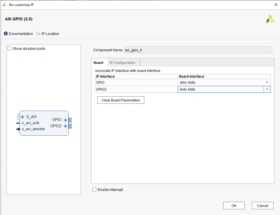
If you are using a custom/non-standard board, the board interface setting should be set to “Custom”. Next, switch to the IP Configuration tab and set everything manually.
If you wish to set the system clock, you can double click on the Processing system block and do so.
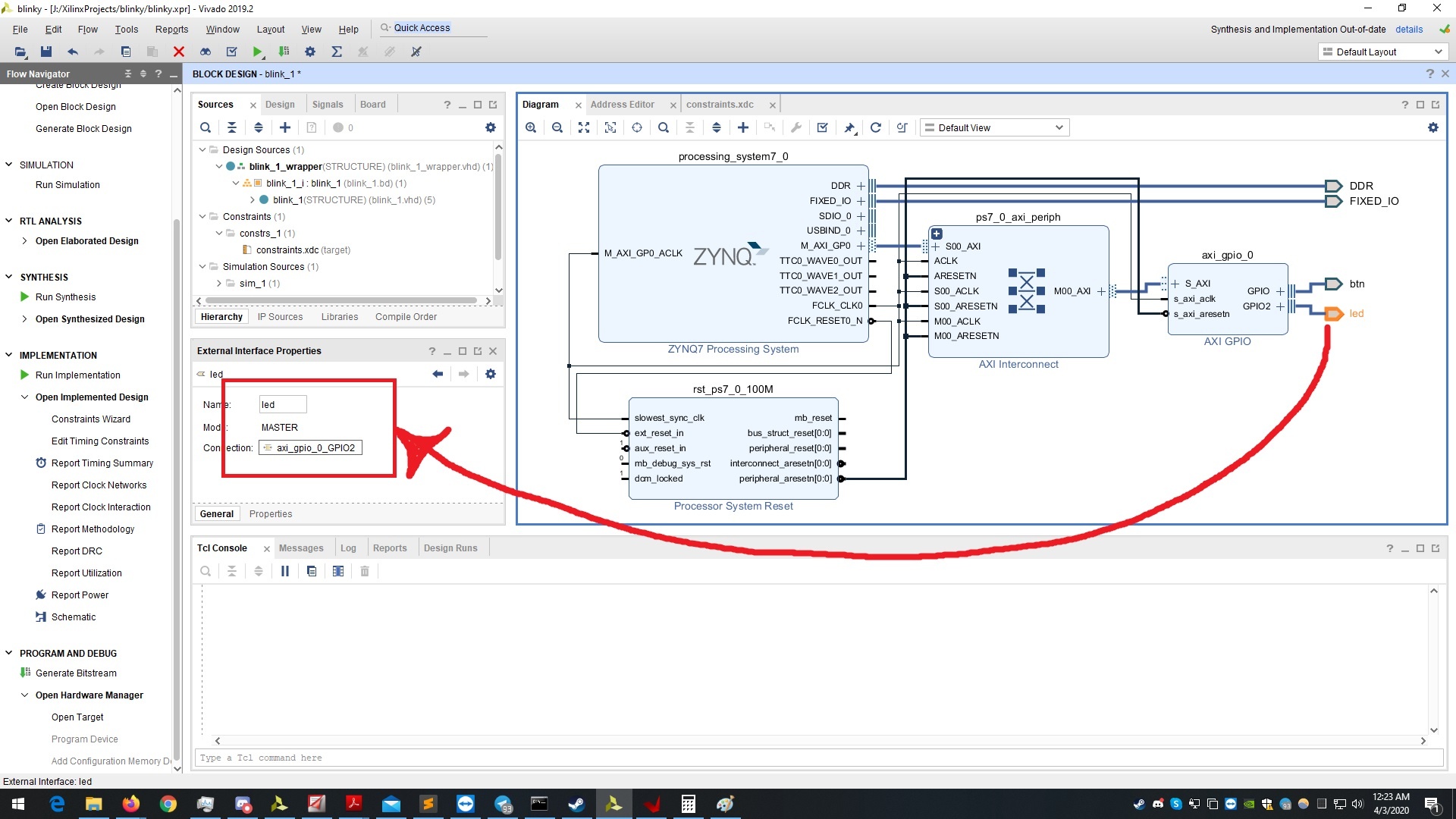
We cannot forget mapping the GPIO signals to the hardware pins. That is done through the constraints file. If you are using a standard board, you can simply place the given constraints file and un-comment the necessary pins.
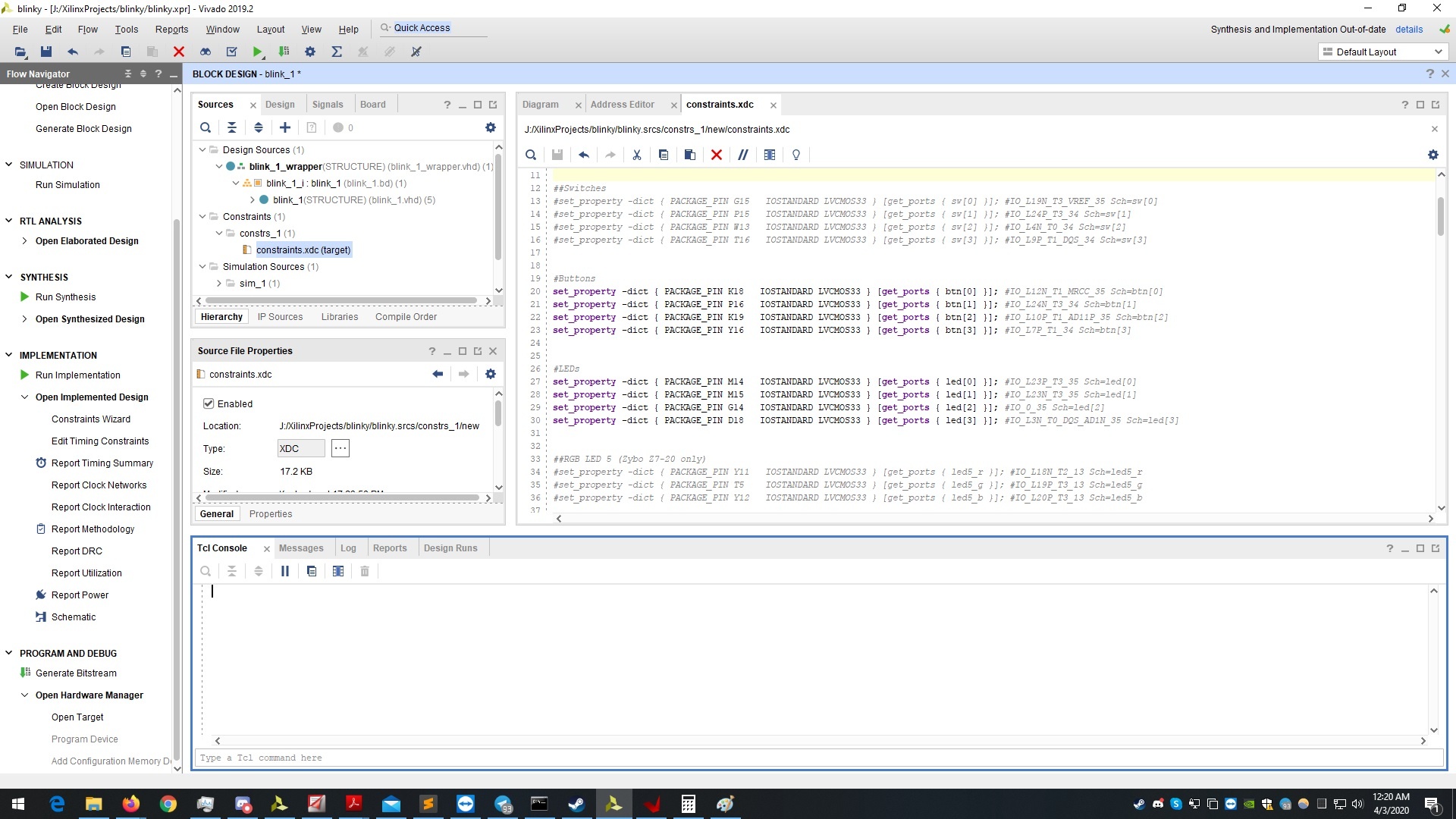
Observe carefully, the part where it says “[get_ports { led[0] }]”. The signal “led” is the name of our GPIO port in the block design. If you happen to make a mismatch in this naming, your signals will never see the real world. Make the settings in the port properties area as shown below.
Synthesis
Looking at the screenshots you may be wondering, where did the blinky_1_wrapper come from? Until now, you should only see the block design and nothing more. Now, right click on the block design and press “Generate output products”. Once that is done, right click again and press “Create HDL wrapper”. Finally, your project space should look similar to mine in the screenshots.
Go the bottom and press “Generate bit stream”. This will initiate the synthesis and implementation process. When the bit stream generation, go to “File > Export > Export hardware” and make sure to “Include bit stream“. Our job with Vivado is done here. We now move to the Xilinx Vitis IDE to configure the rest.
Vitis IDE to program the Zynq processing system
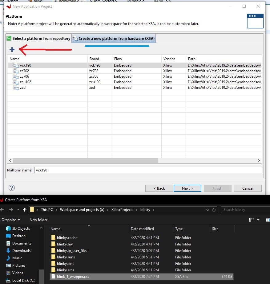
Start your Vitis IDE and import the .xsa file that got generated when we exported the hardware from Vivado. To do this, do the follwing: “File > New application project”. Make sure your project name has no spaces.
Click on “Create a new platform from hardware (XSA)” and then press the “+” icon to import the hardware file we generated in Vivado.
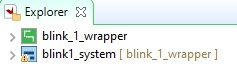
Proceeding further, select “Hello world” or an empty application project. Doing so, we will have two projects created in Vitis IDE. One project is the board support package that contains all the required drivers and definitions. The other project is our application project that will be building on top of the provided BSP.
Expand the blink1_system project and open the “helloworld.c” file. Our aim here is to simply make use of the GPIO peripheral we just created in Vivado and toggle some LEDs.
Some C programming
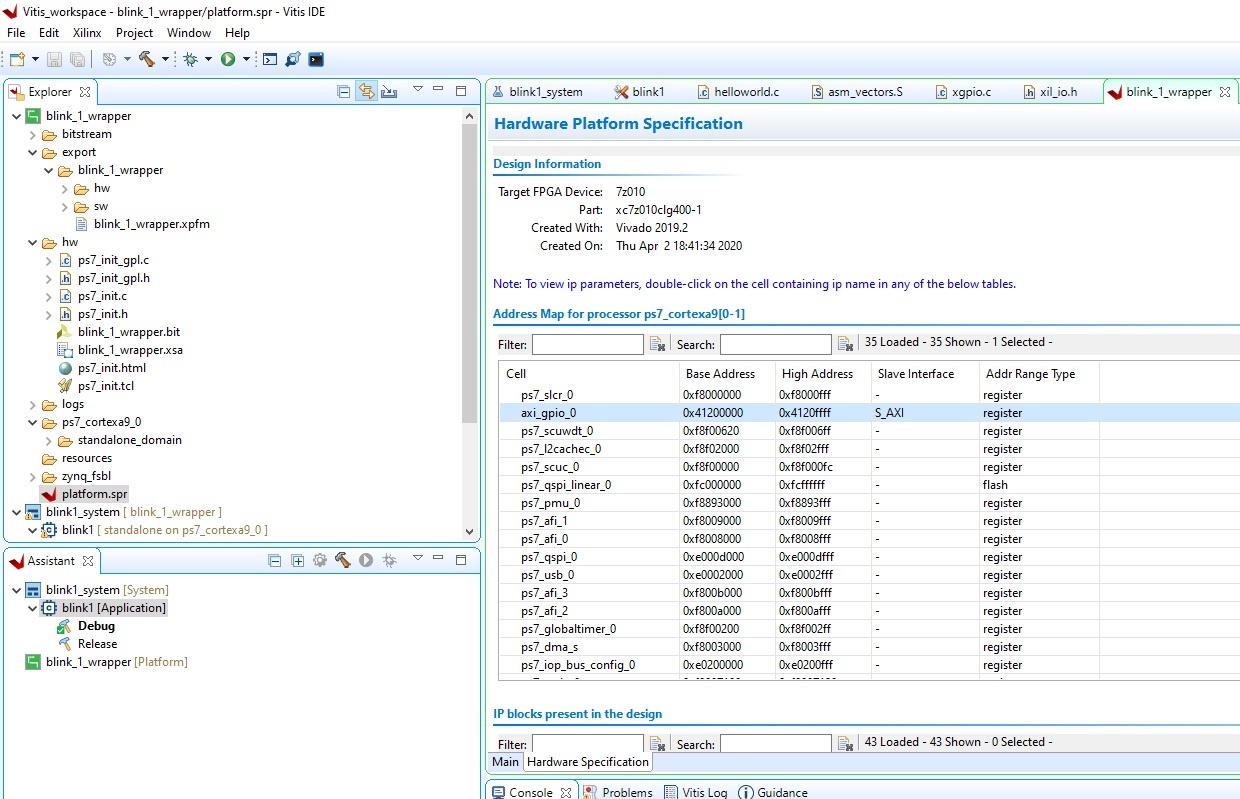
There are two places where you can see the base address of our GPIO block. One is by looking at the properties of the GPIO block in the Vivado design and the other place is looking at the platform.spr file in Vitis IDE.
In order to send data over AXI, Xilinx provides us with Xil_in and Xil_out functions. We can either use those or go for the XGpio functions defined in the xgpio.h file.
Two main functions will help us write to the GPIO peripheral. Firstly, let us initialize a GPIO instance by using the function XGpio_Initialize which takes two arguements. One of the arguments being the instance pointer and the other is device ID. You will find the device ID in xparameters.h file.
We then set the direction of the GPIO using XGpio_SetDataDirection.
|
1 2 3 4 5 |
XGpio gpio; XGpio_Initialize(&gpio, XPAR_GPIO_0_DEVICE_ID); XGpio_SetDataDirection(&gpio, 1, 0x00000000); // set LED GPIO channel tristates to All Output XGpio_SetDataDirection(&gpio, 2, 0xFFFFFFFF); // set BTN GPIO channel tristates to All Input |
Remeber, that we have 4 output pins to drive. All of them are connected to a single GPIO channel called “GPIO” and “GPIO2”. If you don’t remember, go back to Vivado and check it out.
The address to access each channel is fixed. So how do we drive individual LED pins? By setting individual bits in the output register.
|
1 2 3 4 |
#define BIT0 0x01 #define BIT1 0x02 #define BIT2 0x04 #define BIT3 0x08 |
Now, let us drive these leds and see if that works.
|
1 2 3 4 5 6 7 8 |
XGpio_DiscreteWrite(&gpio, 2, BIT0); usleep(100000); XGpio_DiscreteWrite(&gpio, 2, BIT1); usleep(100000); XGpio_DiscreteWrite(&gpio, 2, BIT2); usleep(100000); XGpio_DiscreteWrite(&gpio, 2, BIT3); usleep(100000); |
We are almost done. Click on the debug icon and create a debug configuration. Finally, build your code and debug/Run. You should see dancing LEDs on your board.
|
1 2 3 4 5 6 7 8 9 10 11 12 13 14 15 16 17 18 19 20 21 22 23 24 25 26 27 28 29 30 31 32 33 34 35 36 37 38 |
#include <stdio.h> #include "platform.h" #include "xil_printf.h" #include "xgpio.h" #include "xil_io.h" #include "sleep.h" #define GPIO_BASE 0x41200000; XGpio gpio; #define BIT0 0x01 #define BIT1 0x02 #define BIT2 0x04 #define BIT3 0x08 int main() { init_platform(); XGpio gpio; u32 btn, led; XGpio_Initialize(&gpio, XPAR_GPIO_0_DEVICE_ID); XGpio_SetDataDirection(&gpio, 1, 0x00000000); // set LED GPIO channel tristates to All Output XGpio_SetDataDirection(&gpio, 2, 0xFFFFFFFF); // set BTN GPIO channel tristates to All Input while (1) { XGpio_DiscreteWrite(&gpio, 1, BIT0); usleep(100000); XGpio_DiscreteWrite(&gpio, 1, BIT1); usleep(100000); XGpio_DiscreteWrite(&gpio, 1, BIT2); usleep(100000); XGpio_DiscreteWrite(&gpio, 1, BIT3); usleep(100000); //xil_printf("\rbutton state: %08x", btn); print("Hello World\n\r"); } cleanup_platform(); return 0; |
Thanks for this excellent tutorial – I have managed to get it working on an Arty Z7 board with Vivado 2020.1
However, I thought I’d point out the problem in the source code – the GPIO channel for the LEDs should be 1 and not 2
XGpio_DiscreteWrite(&gpio, 21 BIT0);
usleep(100000);
XGpio_DiscreteWrite(&gpio, 1, BIT1);
usleep(100000);
XGpio_DiscreteWrite(&gpio, 1, BIT2);
usleep(100000);
XGpio_DiscreteWrite(&gpio, 1, BIT3);
usleep(100000);
Thanks for pointing that out!
Thanks for this tutorial, I have question for you. How did you generate your constraint file? Was it provided or did you build it manually?
I got the constraints file from digilent’s github. They have a .xdc for every board they make. You simply need to uncomment the pins/ports that you need.
Other than that, you can also use the schematic and find the pin mapping yourself which obviously be more time consuming.
Hi my friend;
i cant choose “hello world” because it says that i need uart ip for that.
in addition, i keep getting make file error:
make: *** [makefile:39: package] Error 1
You may need to enable UART in your Zynq PS block and then try.
Hello,
I am trying to implement this code on a ZYBO Z7-20
The code builds with no problems but nothing happens on the board itself.
Do you have an idea on what might be the issue.
Thank you
HI, this nagarjuna actually we facing an issue with Zedboard-7000 .when we connect zedboard the done led (LD12) is not blinking and Tera term is also not showing anything .
last time it is displaying some messages .
please help to sort out this problem
Cant really comment without checking the block design. Did you try running simple example projects?