
A basic on screen display with Vivado HLS and Zynq SoC – Part 1
Having an on-screen display in your video can benefit in various ways. Sometimes, having an on-screen display (OSD) can be a need or can serve the purpose of adding an appeal to your project. This little project will be split across two parts. The first part revolves around making a Vivado HLS (High level synthesis) On screen display IP core. In the second part, we will integrate this IP block on to an actual Zynq 7010 SoC. Remember that an ideal OSD will only operate on the desired region. What we are going to do is a very crude method to paint a mask. Nonetheless, it teaches us the basics of the Vivado HLS Video processing library.
Meanwhile, you can also check out other Zynq related articles on this blog.
Designing the HLS On screen display
Our block will accept two inputs over AXI4 Stream interface. One of the stream inputs contains video and the other one contains the mask information. Correspondingly, the third AXI4 Stream interface is the video output.
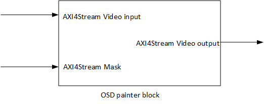
Now that we know what we want to do, let us get started with it. Based on our plan, we need three AXI4 Stream interfaces. Since, we will be operating on 24bit RGB video, each interface will have 24 bit data bus. Additionally, we will also need the AXI4 Stream side-channel but we don’t need to do anything special for it. Vivado HLS takes care of that.
The width and height of the image are another important parameter that we need to define. In this example, we shall operate on a HD 720p video RGB video stream. I have kept a test image and a sample mask ready in the project path because we will be needing it while creating the test bench.
|
1 2 3 4 5 6 7 8 9 10 11 12 |
#define MAX_WIDTH 1280 #define MAX_HEIGHT 720 #define INPUT_IMAGE "J:\\XilinxProjects\\VitisWorkspace3\\stream_mul\\test.bmp" #define MASK_IMAGE "J:\\XilinxProjects\\VitisWorkspace3\\stream_mul\\mask.bmp" #define OUTPUT_IMAGE "J:\\XilinxProjects\\VitisWorkspace3\\stream_mul\\output.bmp" typedef hls::stream<ap_axiu<24,1,1,1> > AXI_STREAM_RGB; typedef hls::Mat<MAX_HEIGHT, MAX_WIDTH, HLS_8UC3> RGB_IMAGE; void painter(AXI_STREAM_RGB &tpg, AXI_STREAM_RGB &mask, AXI_STREAM_RGB &painted); |
Now we can go on and write the painter function. Both the input video streams are first converted into the HLS Mat format. In openCV, the Mat is basically the 2D image matrix. Once, both the streams are forwarded into the Mat variable, we pass it on to the hls::Mul function. This function does pixel by pixel multiplication operation on both the images and the result is sent out in a third Mat variable. Furthermore, this Mat is converted back into AXI4 Stream.
|
1 2 3 4 5 6 7 8 9 10 11 12 13 14 15 16 17 18 |
#include <hls_video.h> #include "core.hpp" void painter(AXI_STREAM_RGB &tpgStream, AXI_STREAM_RGB &maskStream, AXI_STREAM_RGB &paintedStream){ #pragma HLS INTERFACE axis port=paintedStream bundle=OUT_STREAM #pragma HLS INTERFACE axis port=maskStream bundle=MASK_STREAM #pragma HLS INTERFACE axis port=tpgStream bundle=TPG_STREAM #pragma HLS INTERFACE s_axilite port=return bundle=CONTORL_BUS RGB_IMAGE video_in(MAX_HEIGHT, MAX_WIDTH), mask_in(MAX_HEIGHT, MAX_WIDTH), painted_out(MAX_HEIGHT, MAX_WIDTH); #pragma HLS dataflow hls::AXIvideo2Mat(tpgStream, video_in); hls::AXIvideo2Mat(maskStream, mask_in); hls::Mul(mask_in, video_in, painted_out); hls::Mat2AXIvideo(painted_out, paintedStream); } |
Understanding the code
Straight into the code, we can see a bunch of #pragma directives. The first three directives tell the HLS compiler which of the function arguments are AXI4 Stream ports. The bundle directive basically bunches the port signals together. You can literally have any bundle name. The fourth directive is an s_axilite interface. This port is very important to control our HLS block. It will allow us to start and stop the core from the Zynq processing system. Using this same interface, we can also set the image size if we wanted to. We will keep things simple and have the image sized fixed.
Now, you may be wondering that a large image, in this case two of them would need considerable RAM space on the FPGA. Does the Mat really store all that data before multiplication? The HLS compiler operates on pixel by pixel basis. At times, we can define line buffers to store a few lines at the most. A full image is never operated upon.
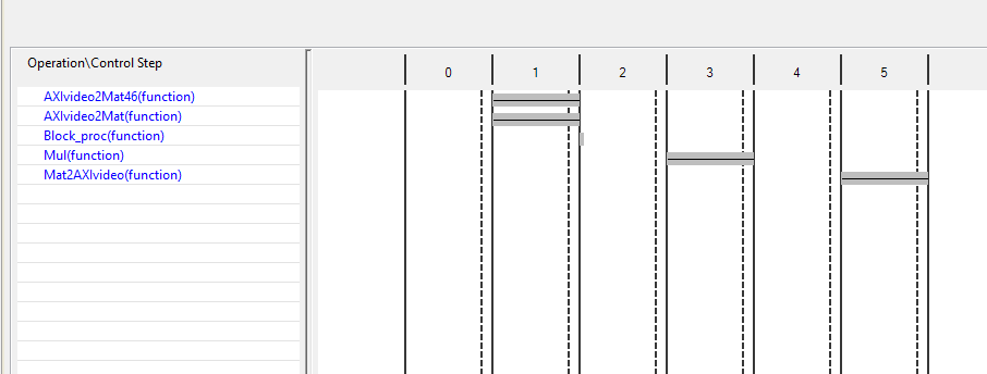
The dataflow directive parallelizes a lot of the functions. Instead of waiting for one function to finish before starting the next one, the HLS compiler passes on the data from one function to the next. Meanwhile, the first function can operate on a new sample and so on.
AXIvideo2Mat function takes in the streaming data. The two bits tuser and tlast in AXI4Stream indicate start of frame and end of line. The mentioned function polls these two bits to align the incoming stream into a correct image. On the other hand, Mat2AXIvideo takes data and places it over AXI4Stream. While doing so, it adds the tuser and tlast bits to indicate SOF and EOL.
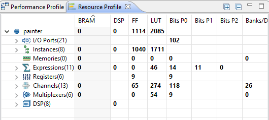
Synthesis Results
The synthesis report gives us an idea about the resources needed on the FPGA. In addition to that, we can also see the data flow pattern and as a result learn about the clock cycles required to do each step in our function. Based on the chart, a pixel will take about 5 clock cycles to come out of the block.
Time to test
Just like any other C++ code, you can call the function in your program and check for correctness in the output. Here, you can do two types of tests. In first test, you will simple verify the functionality in C simulation. Correspondingly, the second test lets you confirm the correctness of auto-generated RTL code based on the RTL co-simulation.
|
1 2 3 4 5 6 7 8 9 10 11 12 13 14 15 16 17 18 19 20 21 |
int main(){ AXI_STREAM_RGB tpgStream, maskStream, paintedStream; IplImage* testImage = cvLoadImage(INPUT_IMAGE); IplImage* maskImage = cvLoadImage(MASK_IMAGE); IplImage* paintedImage = cvCreateImage(cvGetSize(testImage), testImage->depth, testImage->nChannels); IplImage2AXIvideo(testImage, tpgStream); IplImage2AXIvideo(maskImage, maskStream); painter(tpgStream, maskStream, paintedStream); AXIvideo2IplImage(paintedStream, paintedImage); cvSaveImage(OUTPUT_IMAGE, paintedImage); cvReleaseImage(&testImage); cvReleaseImage(&maskImage); cvReleaseImage(&paintedImage); return 0; } |
I generated a simple mask image in Paint. The whole image is first filled with RGB: 0x010101. By doing so, I will be basically multiplying the whole image by 1. In short, doing no change to the image. Then I type some text with RGB: 0x000000. The pixels in resulting text area will appear black. As a result we will be imprinting the mask onto the video frame.


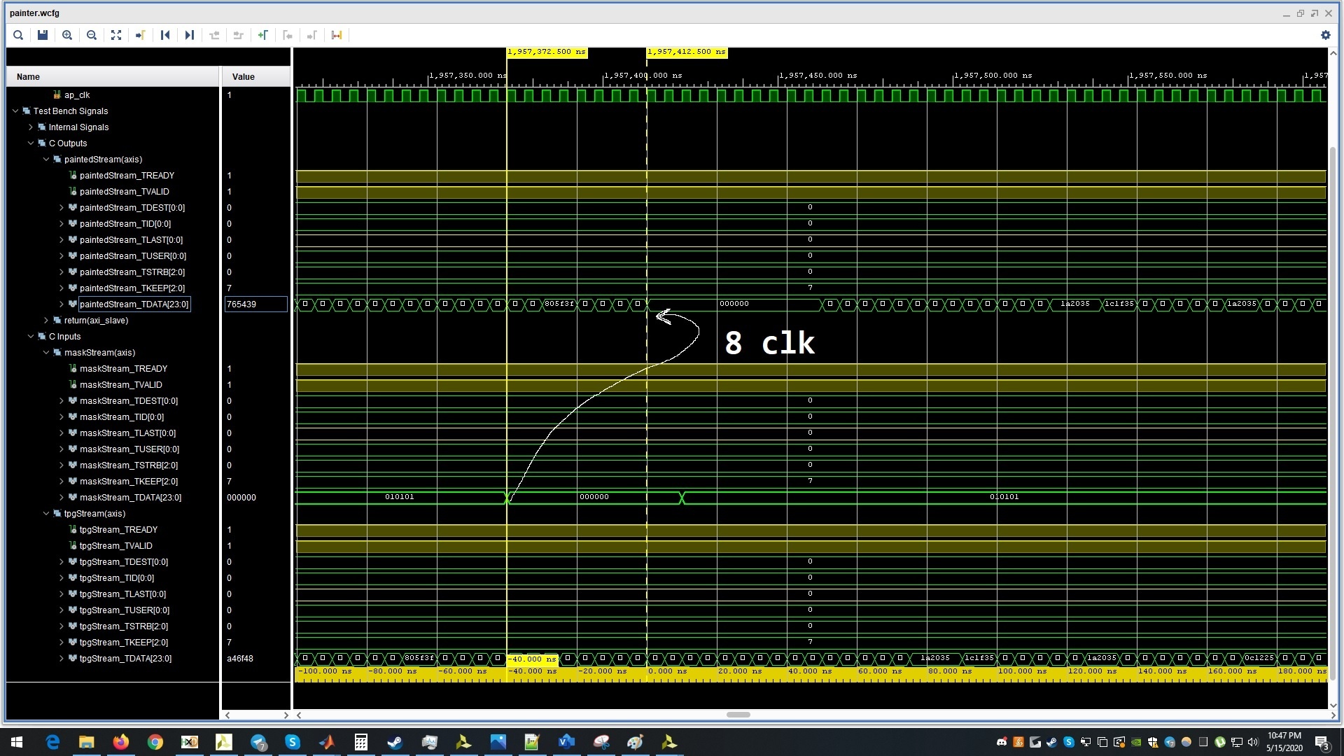
Seems like it is working. Now, I will do a RTL Co-simulation and observe the waveforms.
Observing RTL-Cosimulation results
Before you begin the co-simulation, make sure the settings are as follows:
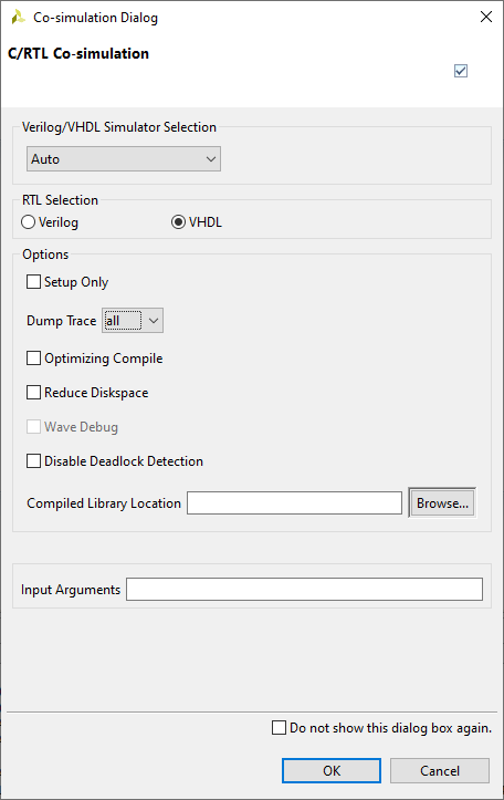
Looking at the results, we can see that the data takes about 8 clock cycles to come out. Apparently, there is a slight discrepency in the synthesis result and the actual RTL result. We wont’ be trying to go into this. That’s for some other article.
The results seem correct and promising. In the next part of this tutorial, we will export this HLS block into Vivado for integrating it with VDMA and observe the output on a real screen.
All three source code files are uploaded to my Github account.
Hello, I’ve been working on a video processing project targeted the Zynq device on a custom FPGA development board, I’m unable to obtain the output of hls::Mul step when I run the codes on SDK.(on hardware-custom FPGA board)
There is an input VDMA with read channels enabled and an output VDMA with write channels enabled connected across the input and output of the HLS IP core.
Here are my codes:
#include “top.h”
void dust_detect(AXI_STREAM& input_data, AXI_STREAM& output_data)
{
#pragma HLS DATAFLOW
//Create AXI streaming interfaces for the core
#pragma HLS INTERFACE axis port=input_data
#pragma HLS INTERFACE axis port=output_data
#pragma HLS INTERFACE ap_ctrl_none port=return
/************* Arrays used ***************/
gray_IMAGE img_0;
#pragma HLS STREAM variable=img_0
gray_IMAGE img_1;
#pragma HLS STREAM variable=img_1
gray_IMAGE img_2;
#pragma HLS STREAM variable=img_2
gray_IMAGE img_2a;
#pragma HLS STREAM variable=img_2a
gray_IMAGE img_2b;
#pragma HLS STREAM variable=img_2b
gray_IMAGE img_3;
#pragma HLS STREAM variable=img_3
gray_IMAGE img_4;
#pragma HLS STREAM variable=img_4
gray_IMAGE img_5;
#pragma HLS STREAM variable=img_5
gray_IMAGE img_6;
#pragma HLS STREAM variable=img_6
gray_IMAGE img_7;
#pragma HLS STREAM variable=img_7
const char coefficients1[7][10] = { { 1, 1, 1, 1, 1, 1, 1, 1, 1, 1},
{ 1, 1, 1, 1, 1, 1, 1, 1, 1, 1},
{ 1, 1, 1, 1, 1, 1, 1, 1, 1, 1},
{ 1, 1, 1, 1, 1, 1, 1, 1, 1, 1},
{ 1, 1, 1, 1, 1, 1, 1, 1, 1, 1},
{ 1, 1, 1, 1, 1, 1, 1, 1, 1, 1},
{ 1, 1, 1, 1, 1, 1, 1, 1, 1, 1} };
hls::Window erodewindow;
for (int i=0;i<7;i++){
for (int j=0;j<10;j++){
erodewindow.val[i][j]=coefficients1[i][j];
}
}
const char coefficients2[9][12] = { { 1, 1, 1, 1, 1, 1, 1, 1, 1, 1, 1, 1},
{ 1, 1, 1, 1, 1, 1, 1, 1, 1, 1, 1, 1},
{ 1, 1, 1, 1, 1, 1, 1, 1, 1, 1, 1, 1},
{ 1, 1, 1, 1, 1, 1, 1, 1, 1, 1, 1, 1},
{ 1, 1, 1, 1, 1, 1, 1, 1, 1, 1, 1, 1},
{ 1, 1, 1, 1, 1, 1, 1, 1, 1, 1, 1, 1},
{ 1, 1, 1, 1, 1, 1, 1, 1, 1, 1, 1, 1},
{ 1, 1, 1, 1, 1, 1, 1, 1, 1, 1, 1, 1},
{ 1, 1, 1, 1, 1, 1, 1, 1, 1, 1, 1, 1} };
hls::Window dilatewindow;
for (int i=0;i<9;i++){
for (int j=0;j<12;j++){
dilatewindow.val[i][j]=coefficients2[i][j];
}
}
/******************* Step-1 of Dust Detection Algorithm ************************/
hls::AXIvideo2Mat(input_data, img_0);
hls::Threshold(img_0,img_1,80,255,HLS_THRESH_BINARY);//OTSU THRESHOLDING
hls::Threshold(img_1,img_2,100,255,HLS_THRESH_BINARY_INV);//Invert the Thresholded output
hls::Duplicate(img_2,img_2a,img_2b);
/******************* Step-2 of Dust Detection Algorithm ************************/
hls::Erode(img_2a,img_3,erodewindow);
hls::Dilate(img_3,img_4,dilatewindow);
hls::Threshold(img_4,img_5,100,255,HLS_THRESH_BINARY_INV);//Invert the Dilated output
hls::Threshold(img_5,img_6,100,1,HLS_THRESH_BINARY);
hls::Mul(img_2b,img_6,img_7);
hls::Mat2AXIvideo(img_7,output_data);
}
*********************
top.h :
#ifndef _TOP_H_
#define _TOP_H_
#include “hls_video.h”
#define INPUT_IMAGE “reed_in.bmp”
#define OUTPUT_IMAGE “inverted_dilate_out.bmp”
#define MAX_HEIGHT 2764//288//2764//720//576//200//576
#define MAX_WIDTH 3856//720//3856//1280//720//200//720
typedef hls::stream<ap_axiu > AXI_STREAM;
//typedef hls::stream<ap_axiu > AXI_STREAM_8;
//typedef hls::Mat GRAY_IMAGE;
typedef hls::Mat gray_IMAGE;
void dust_detect(AXI_STREAM& input_data, AXI_STREAM& output_data);
#endif
***********************
testbench:
#include “Top.h”
#include
void dust_detect(AXI_STREAM& , AXI_STREAM& );
int main (int argc, char** argv) {
IplImage* src = cvLoadImage(INPUT_IMAGE,0);
IplImage* dst = cvCreateImage(cvSize(MAX_WIDTH, MAX_HEIGHT),8,1);
AXI_STREAM src_axi;
AXI_STREAM dst_axi;
IplImage2AXIvideo(src, src_axi);
dust_detect(src_axi, dst_axi);
AXIvideo2IplImage(dst_axi, dst);
cvSaveImage(OUTPUT_IMAGE, dst);
cvReleaseImage(&src);
cvReleaseImage(&dst);
return 0;
}
Kindy pls help me out with what I could be missing in the codes.
You need to be more specific about the inputs to your HLs block for me to start thinking about it.
Will I be able to run the same code as above on Vitis HLS ?
Won’t work directly. You will need some changes in the code to adapt.
The input to HLS IP is a grayscale 10MP(3856*2764) image.