
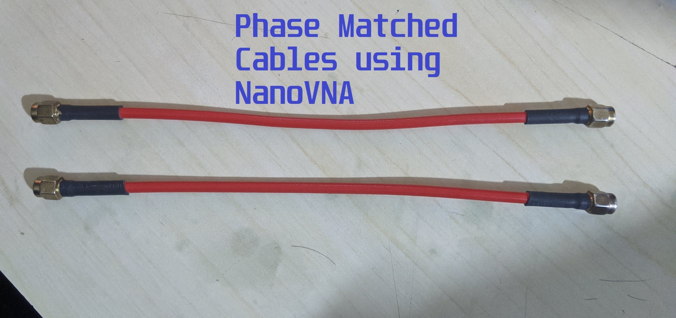
Make your own Phased Matched cables with NanoVNA
Phase matched cables come handy when dealing with phasing elements of an antenna or even when you want to deliver differential signals. There was a time when making phase matched cables meant use of expensive vector network analyzers. With the NanoVNA on your desk, you can make your own cables. If you don’t know about NanoVNA, you should head back to our review.
Check my other NanoVNA articles:
Review
The Comparison with Keysight N9952A VNA
TDR Script
Cable Impedance measurement
The cross dipole and delivery of differential signals are the two prominent examples that pop into my head. Both applications require cables with precise phase delay. In case of cross-dipole (a.k.a. turnstile antenna) you need a phasing element that provides \(90^o\) phase shift between the two dipoles. Often times, that phasing element is made out of a coaxial cable. The second example requires two cables having absolutely equal phase. A little phase imbalance leads to generation of common mode currents going through the system.
A third example which popped into my mind while writing is the “phased array antennas“. A lot of our fellow hams use antenna arrays to increase the directive gain and reach further out in the desired direction. Suppose you have 4 yagi antennas and one transceiver. There will be a splitter/combiner which will split and combine the transmit and received signals respectively. All cables running from the splitter towards the antenna array need to have equal phase. Otherwise, you will end up with a squinted antenna that radiates power several degrees in the wrong azimuth/elevation angle.
In this article, I will explain how to make phase matched cables that have equal phase delay.
A little dive into the basics
In the industry, phase matched cables are made with the help of expensive two port VNAs. Two ports because both the ports can show you the reflection coefficient. In our nanoVNA, we will need to focus on one cable at a time because here we can only see the reflection coefficient (\(S_{11}\)) on one of the ports.
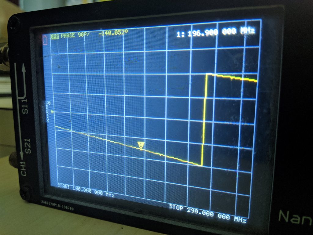
The reflection coefficient \(S_{11}\) tells is a complex value. Meaning, it gives us the magnitude and phase information about the reflected signal. In this application, we need to make use of the phase information. The phase of the signal will increase linearly with frequency from \(+180^o\) to \(-180^o\). Although, we can make use of this phase information directly, it could lead to some errors while tuning our cables. On the other hand, the nanoVNA has the option to use the “Delay” function which is basically a differentiation of consecutive phase values.
\(Delay=\frac{-1}{360^o}\times\frac{\Delta\omega}{\Delta f}\)Where \(\Delta\omega\) is the difference of consecutive phase values. In short, we are differentiating the phase with respect to frequency.
Consider a slope which goes linearly increasing in value. This slope is divided into 10 points. If you subtract two adjacent points, you will always land with the same value. That’s because the slope is linear and constant. Difference between consecutive points is exactly what differentiation is all about and you run this across the entire length of the slope/line/curve.
Constructing phase matched cables
We have seen how to find the delay of the cable. This knowledge will come handy as we start constructing phase matched cables. There are two main requirements for such a cable pair. The first requirement is the obvious equivalent phase delay. On the other hand, the second requirement is usually the length of the cable.
In this experiment, I will be attempting to make a pair of phase matched cables 20cm in length. I will be using the RG402 cable and straight SMA connectors. Please note that I won’t be showing you the process of soldering the connectors. On the contrary, I would be more focused on the actual point of this article which you already know if you have come this far.
1. Cut two lengths of RG402 22cm long. Make sure both the cables are from same spool.
2. Strip off and solder straight SMA connectors on one of the ends of each cable. Do not solder connectors on both the ends yet.
3. Once you are done soldering, you will end up with cables having connector at one end. The other end should remain without connector.
Now comes the fun
Fire up your NanoVNA or any VNA that you might own. Choose the frequency range of your choice and calibrate it. One port calibration is sufficient. If you want to operate in the VHF and the lower UHF band (<500MHz), you are fine. If you intend to achieved phase match on anything more than 700MHz, you might need a better VNA such as the NanoVNA V2 (SAA2) or something more expensive. The reason being, you need to be very very precise at higher frequencies. The wavelengths get smaller and as a result, a few millimeters could mean several tens of degrees in phase shift!
It is absolutely important to label your cables. Let us start with the cable #1. Connect it to the port 1 of your NanoVNA and measure the delay. If you don’t know how to activate this function follow this: Menu > Display > Format > Delay. You also need to make sure you selected the right trace or you might end up activating this function on the wrong trace. You specifically need to activate this function on the CH0 channel.
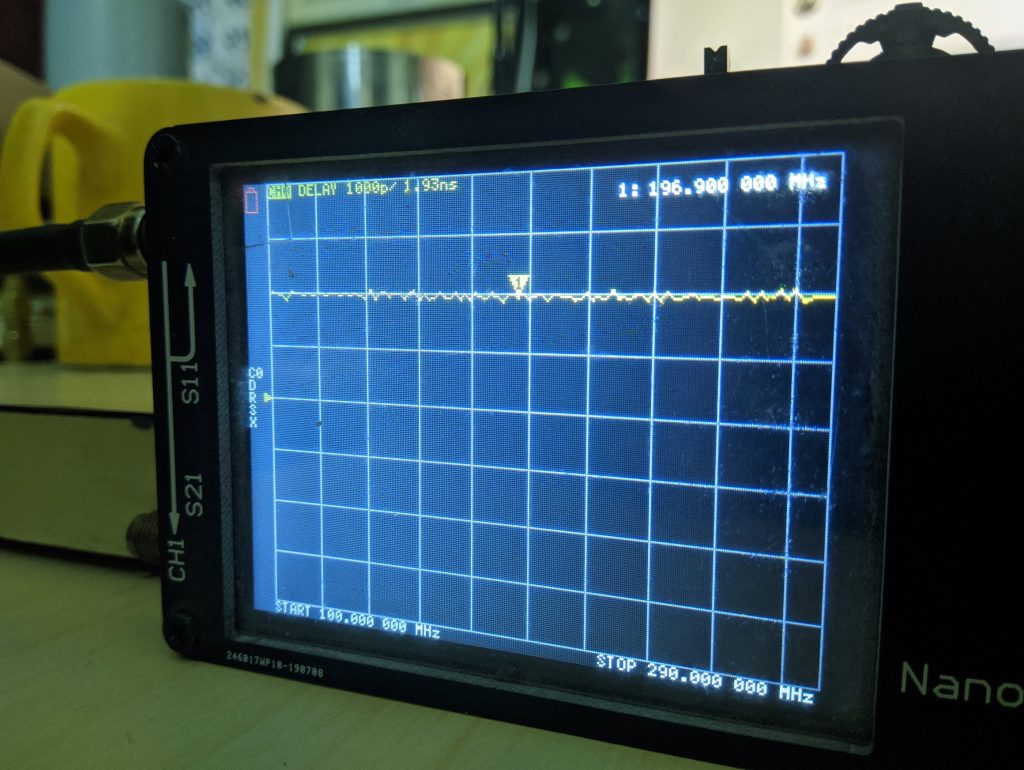
If your cable has come from a good source, you should see a flat trace as below.
Note down the delay somewhere on a piece of paper. Here, you can see I got a reading of 1.93ns on the cable #1.
Carry out the same measurement for cable #2. Note the reading on the paper. I got a delay measurement of 1.90ns on my second cable.
What can you say about the two cables now? The first cable is obviously longer than the second one by a tiny margin. Now, our aim is to bring the longer cable to have same delay as the second one. An error of 0.03ns seems absolutely negligible at 200MHz. On the other hand, at 500MHz, it becomes significant enough to be bothered about. Let us quantify this through some math.
Dive in to the math
\(T = \frac{1}{150\times10^6} = 5ns\).
It takes 5ns for one cycle to complete at 200MHz. This means, it takes \(5ns\) to rotate entire 360 degrees for a cycle to finish.
Time taken to cover one degree \( = \frac{5ns}{360^o} = 13.88ps \).
Now, we know that the time difference between the two cables and we want to find out what it means in terms of degrees.
Phase shift \( = \frac{0.03ns}{5ns}\times 360^o = 2.16^o\)
If we repeat the process for a frequency of 500MHz, you replace 5ns with 2ns, you get a phase shift of 5.4 degrees. Similarly, at 1GHz it becomes whopping 10.8 degrees. In short, you need to be precise in cutting your cable at higher frequencies. For someone working with antenna arrays, even 5 degree phase shift in one of the cables can affect antenna performance to some extent. The effect would be generation of unwanted side lobes or beam squint.
In terms of distance, we need to use the above results in another simple formula.
Wavelength in the cable is governed by the velocity factor. The RG402 has a velocity factor of 71%.
Therefore, \(\lambda_g = \frac{c}{f}\times v_p\). For a frequency of 200MHz, the \(\lambda_g = 1.065m\).
Length for 1 degree = \(\frac{1.065}{360^o} = 2.95mm\).
Using the same concept above, we can find the length for any arbitrary phase shift. Earlier, we calculated that the difference between two cables is 2.16 degrees at 200MHz. This equates to a length of \(\frac{1.065m}{360^o}\times 2.16^o = 6.39 mm\).
Just to be safe, cut the cable a millimeter or two less than the calculation just to be sure. You can do this while the cable is still connected to your VNA. If the delay drops and matches the shorter cable, you are good to go. Otherwise, you may trim a bit more and try to get it matched.
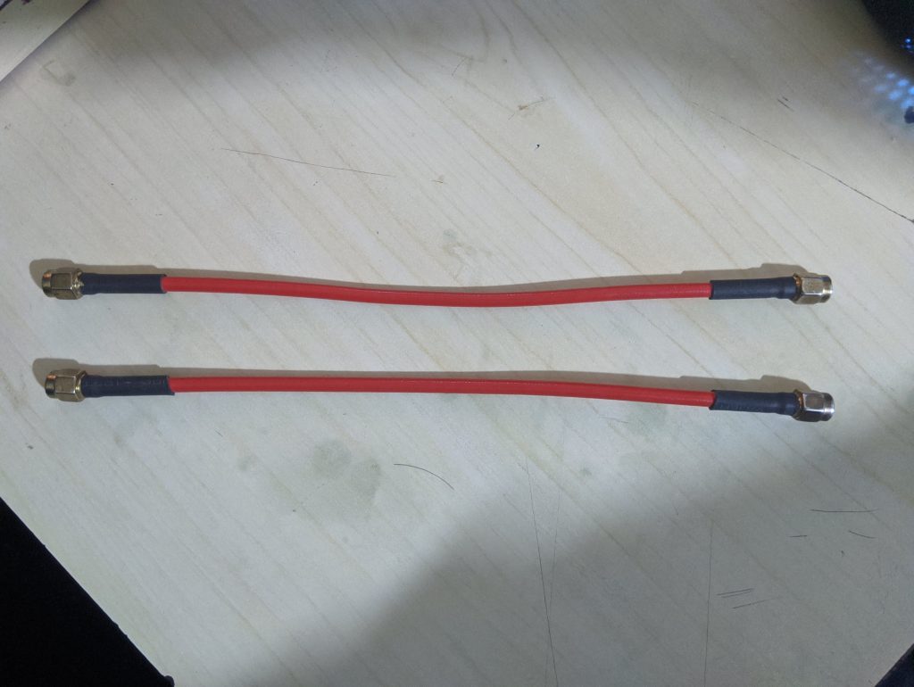
Finally, attach connectors to both the ends and measure the delay on your VNA. If you did it all correctly, you should end up with perfectly phase matched pair of cables. You may repeat the steps to create more of such cables if you are working on an antenna array or some thing with similar requirement.

Always wondered how these cable are made thank you for the explanation.
Nice tutorial. How would this method work for matching a cable over a wide frequency range? For example, if I want to match the cable for frequencies from 100 to 200 MHz, will matching it at 150 MHz ensure it is matched for the other frequencies within this range? What changes would be needed in the method to achieve this?
You should match it at the highest frequency. That should do.