
Building an automatic gain control (AGC) circuit
Most amplifiers we use have a fixed gain. In case of excess input power, the amplifier saturates. As a result, the blocks down the receive chain also get affected by this. To avoid this, the preferred technique is to reduce the gain of the amplifier or even attenuate the input. Now, the gain of this amplifier block can be controlled in several ways. One method is to detect the RF power and have the analogue control signal to manipulate the amplifier gain. In another approach, the detected RF, which is a DC signal, is fed back to the analogue attenuator, which could be a PIN diode. While in some cases, we use a digital attenuator instead of an analogue one. Now that you have understood the purpose of automatic gain control (AGC) let us proceed further.
AGC System overview
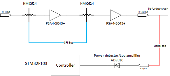
In this short article, we will be looking at a very crude automatic gain controlled (AGC) amplifier built using a digitally controlled attenuator. Have a look at the following block diagram depicting the system.
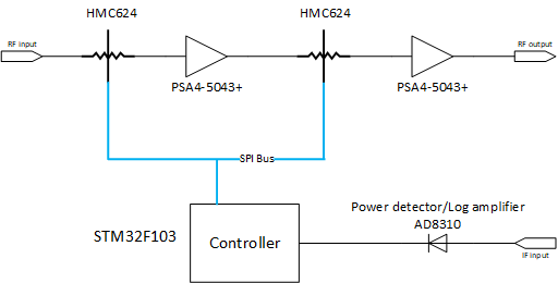
Our system consists of two HMC624 digitally controlled attenuators, two PSA4-5043+ gain blocks, one AD8310 log detector and one STM32F103 microcontroller. The HMC624 digital step attenuators have both parallel and Serial programming interfaces setting the attenuation value. To reduce the number of lines, I have used the SPI interface. On the other hand, the AD8310 log amplifier is fed with IF (intermediate frequency) signal and it outputs a proportional DC level. Further, the ADC of the microcontroller reads the DC signal coming from the log-detector.
Some more component details
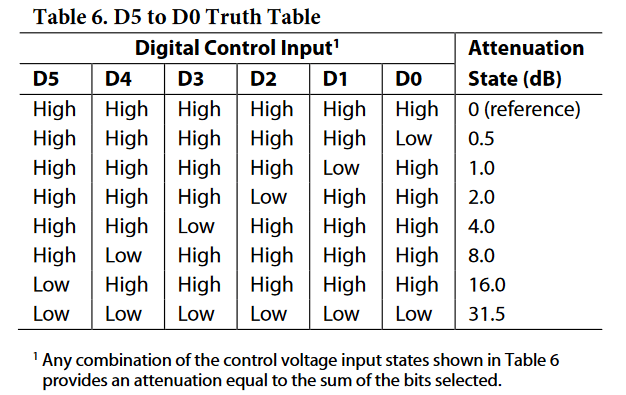
To elaborate a little more on the circuit blocks, the PSA4-5043+ gives a gain of 21dB at 400MHz. Two of them in series results in a total achievable gain of 42dB. The HMC624 digital step attenuators offer a maximum attenuation of 31.5dB in steps of 0.5dB. In other terms, it offers a 6-bit resolution. Two of them in the signal path can give us a maximum attenuation of 63dB.
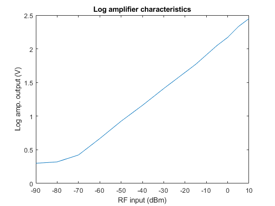
My aim here was to maintain the output signal level at -10dBm. After looking at the log amplifier characteristics, -10dBm power results in a DC voltage of approximately 2.0V.
We are running an elementary algorithm on the microcontroller. Check out the following algorithm.
- Initially set 0dB attenuation.
- Measure the log amplifier output using microcontroller’s in-built ADC.
- If the measured DC value is greater than 2.0V, increase the attenuation by 1dB.
- Else, if the measured DC value is less than 1.95V, decrease the attenuation by 1dB.
- Return to step 3.
While reducing the attenuation, I have set the DC value 0.5V lower. Doing this gives us an effect of hysteresis. Not having hysteresis will result in fluctuating attenuation. As a result, the output will also switch in the range of \(\pm 1dB\).
The code
Before writing the code, I configured the STM32F103 microcontroller in CubeMX tool by defining the pins connected to SPI, ADC and so on. I generated the underlying code with CubeMX and took that as a starting point. The next thing on the list are the two HMC624 digital step attenuators. I needed to know whether they were behaving as expected. I started to write a C function to compute the attenuation register value as defined in the datasheet.
The register setting is quite simple. It is a 6-bit inverted value. Read below to see how I wrote it in C.
|
1 2 3 4 5 6 7 8 9 |
uint8_t calculate_attenuation_register(ATTN_REG reg, float attenuation){ uint8_t att; if(attenuation <= 31.5){ attenuation = ceil(2.0 * attenuation); att = (uint8_t)(attenuation); reg.w = ~(att); } return reg.w; } |
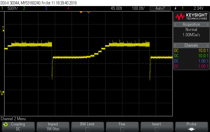
In order to test the attenuators, I incremented the attenuation value in steps of 0.5dB while giving a constant input signal. I observed a stepped ramp being generated as a result of linearly varying attenuation. Apparently, the HMC624 were working the way they should.
Coming back to the function, I pass an attenuation value in float format and check whether the value is in the expected attenuation range of 31.5. I multiply it by two and obtain the nearest integer. The attenuator can be configured in steps of 0.5dB and that’s the reason we multiply it by two so that we can get the full 6-bit range. Finally, we invert the value before returning it to the calling function.
According to the datasheet, the HMC624 expects the data to be 6-bit in size. Anything more gets pushed out from the MISO pin. For example, we are pushing 8 bits instead of 6 results in 2 extra bits being flushed out from the serial out pin. There’s simply no need to manipulate the bits. Simply write the eight whole bits and transfer over SPI. Since we are doing an MSB-first transaction, the excess 2 bits would won’t matter.
The control loop looks something like this.
|
1 2 3 4 5 6 7 8 9 10 11 12 13 14 15 16 17 18 19 20 |
while(1) for(i=0; i<20; i++){ HAL_ADC_PollForConversion(&hadc1, 10); detector_val += HAL_ADC_GetValue(&hadc1); } detector_val = detector_val/20; detector_val = (detector_val + prev_detector_val)/2.0; detector_volt = detector_val * 3.3/4096; if(detector_volt > 2.0){ att_val = att_val + 1.0; } else if (detector_volt < 1.95){ if(att_val > 1.0){ att_val -= 1.0; } } reg.w = calculate_attenuation_register(reg, att_val/2.0); set_attenuation(reg.w); prev_detector_val = detector_val; } |
The results
To observe the response of our simple little AGC circuit, we need to sweep the input amplitude of the signal. Just for test purpose, I have used the same signal frequency for the RF input port and the detector input port.
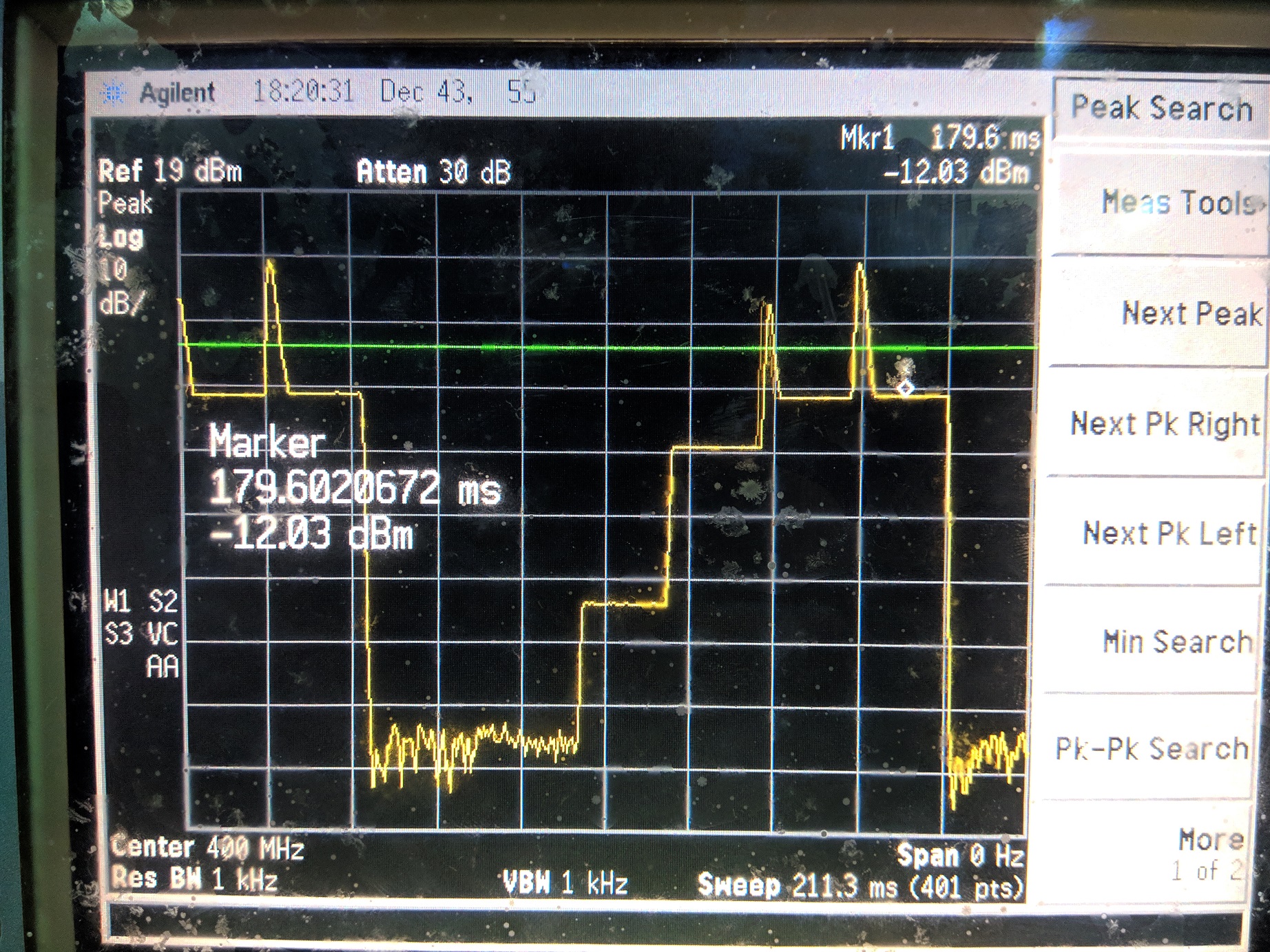
The RF source sweeps the signal amplitude from -100dBm to 0dBm in 5 steps. We will then observe the output on the spectrum analyzer. Since we are interested in the output amplitude of the signal, we will be watching the signal in ‘Zero Span’ mode. On the other hand, we can also observe the detector output on an oscilloscope.
There are several algorithms one can implement on this closed-loop system. I have barely brushed the surface of it. Perhaps, I could look to implement a more sophisticated algorithm in the future.
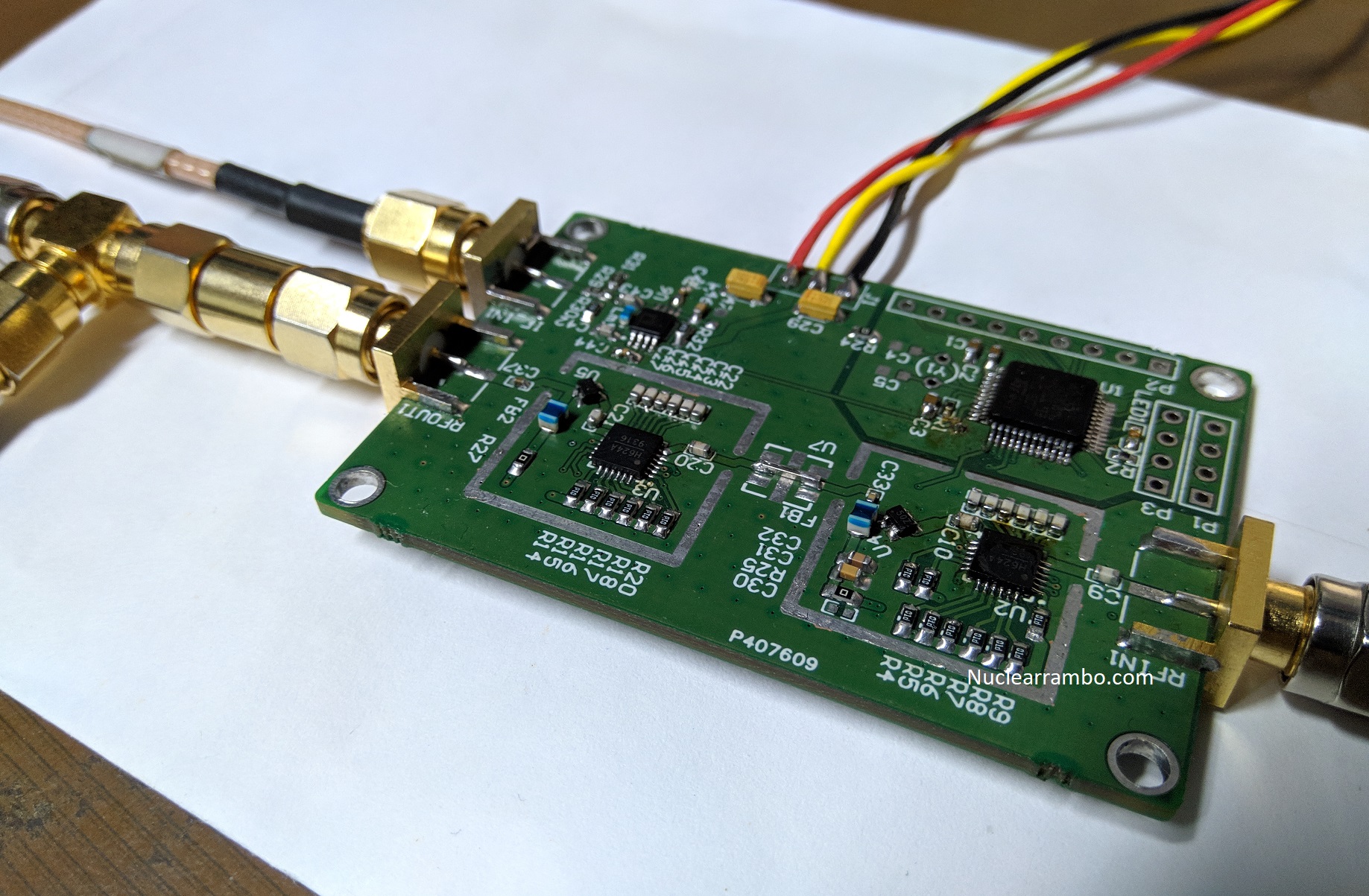
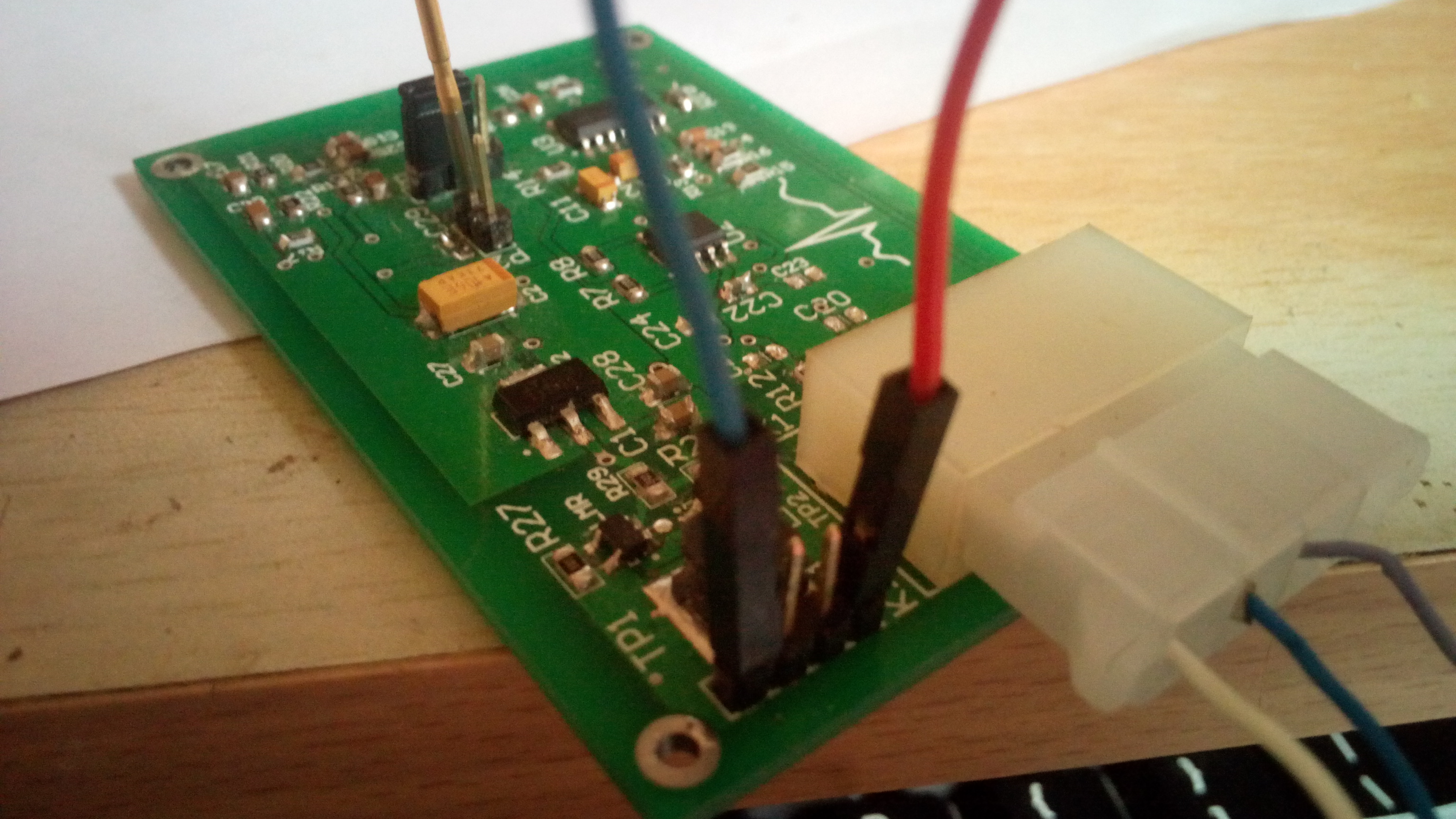
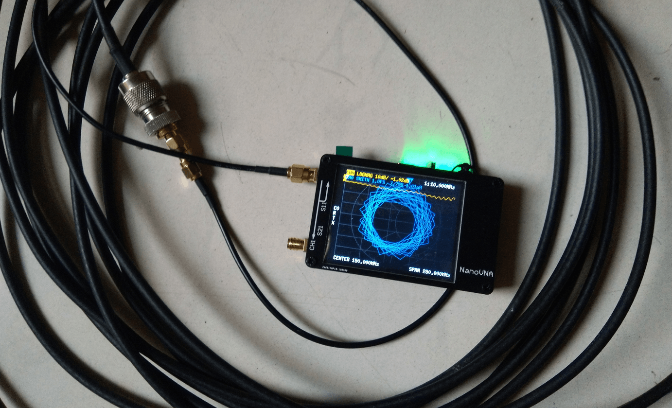
Before you go, have a look at the AGC circuit.
Good one
Nice. Thanks sharing! 73 PA5OXW
More amplifiers, maybe you can know more from ichome