
Using LimeSDR mini as a RF source
In one of the previous posts we saw how we could transmit DATV using LimeSDR mini. This time we are going to use our LimeSDR mini as a RF source in our home lab. The whole setup is based on GNU Radio and the QT Gui that comes with it. Operating all the way from 10MHz to 3.5GHz, this SDR can serve as a RF source while testing your circuits. Remember that this is a makeshift RF source for those who don’t own one, such as my self. This is going to prove quite useful to me while doing my experiments. This post is going to be really short one because the method is so simple and straight forward if you have the basic drivers and stuff all setup correctly.
The basic setup
All you need is a LimeSDR mini, a PC and a RF cable. You will need to install GNU Radio on your PC which you can download from the official website.
You will need to create a simple schematic and add the following blocks.
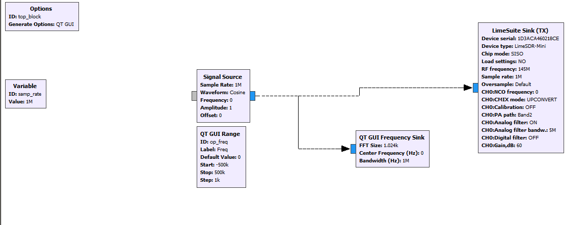
The schematic contains 4 main blocks.
The signal source having a sample rate of 1MHz. This sample rate can be more or less depending on what you need. You can go all the way up to 30MHz. This sample rate decides the tuning range of your RF source. For example, if you set the sample rate to 1MHz, the tuning range will be +500kHz around the center frequency set by the LimeSuite TX block.
QT GUI Range block will let you set the start and stop frequency of your RF source which I have kept +500kHz based on the sample rate I have selected. It could be more or less in your case. I have also set the ID of this block as “op_freq”. Now open the Signal source block and enter “op_freq” in the frequency field. Now, this links the Signal source and the QT GUI range block allowing you to change the frequency through the GUI.
Finally, LimeSuite TX block will interface the rest of our schematic to the real world. This block demands you to enter the LimeSDR Mini serial number which you will find in LimeSuite utility. Set your desired frequency in the “RF Frequency” field and the sample rate can be anything up to 30MHz. Make sure the sample rate matches the sample rate of rest of the blocks. If not, you might end up generating wrong frequency at the output. Now, in the CH0 tab, you will need to set “CMIX Mode” as “upconvert”. This is because we are generating low frequency, base band signal and we need to end up with something in the RF range.
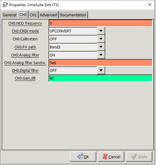
You do not need the Digital filter, so that can be kept OFF. On the other hand, the analog filter cut off frequency needs to be set according to the tuning range. If you generate a 1MHz base band signal and the analog filter bandwidth is set to 500kHz, you would see a weak signal at the output and start blaming the SDR device. Furthermore, the “Gain” field can be set anything up to 100dB. Too low of a gain value will also result in a weak signal at the output.
Testing
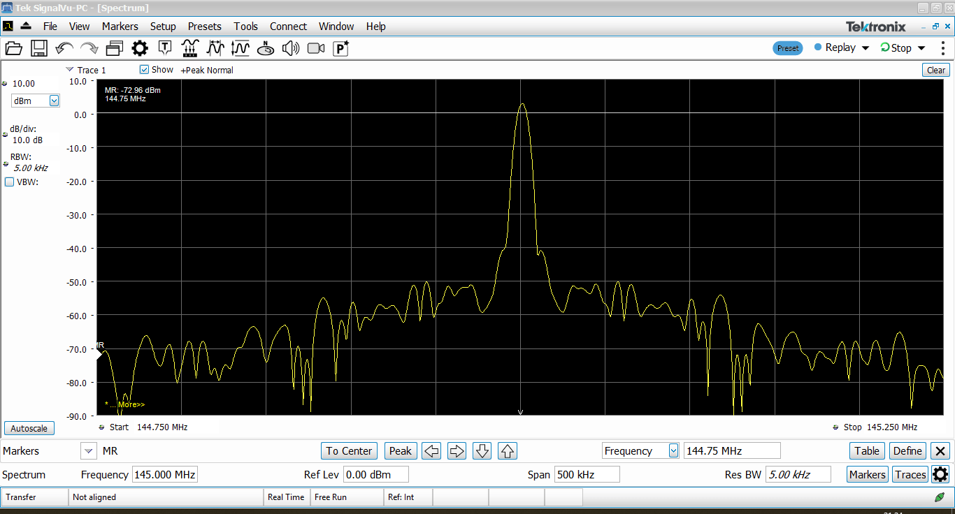
After the schematic is ready, you can hit run and observe the output. Fortunately, I have access to a nice little Tektronix RSA306B real time spectrum analyzer and I would be using this to observe the spectrum. If you don’t have a spectrum analyzer you would plug in a RTL-SDR and observe the spectrum there. Alternately, you could also use the LimeSDR Mini itself to observe the signal it generates by plugging in a RX block in the schematic.
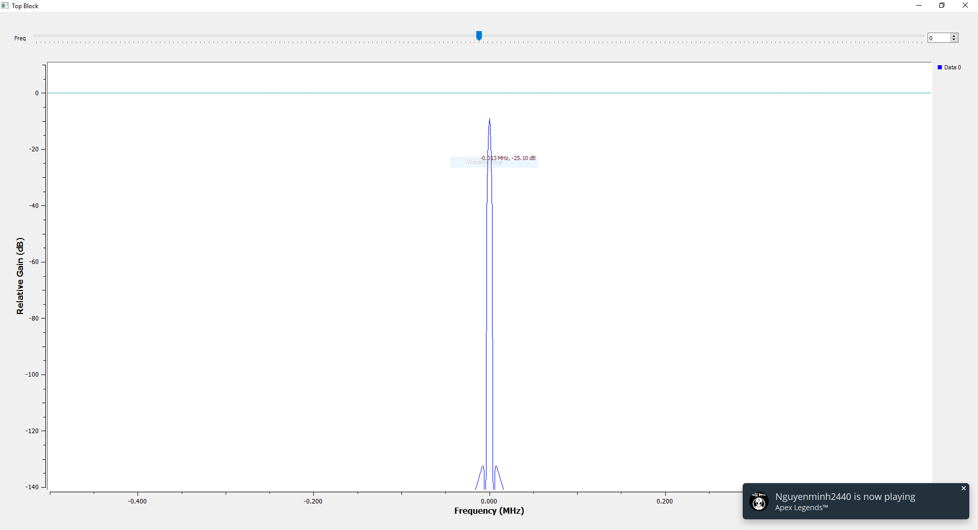
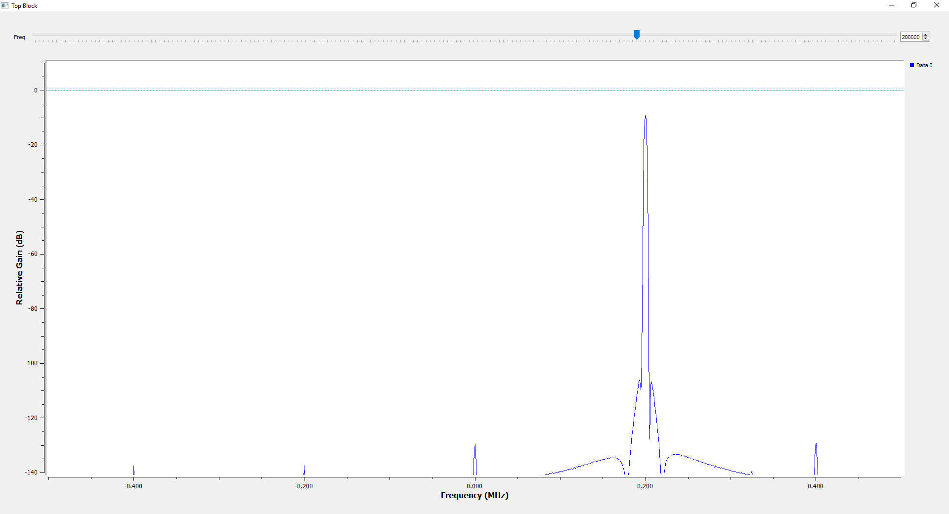
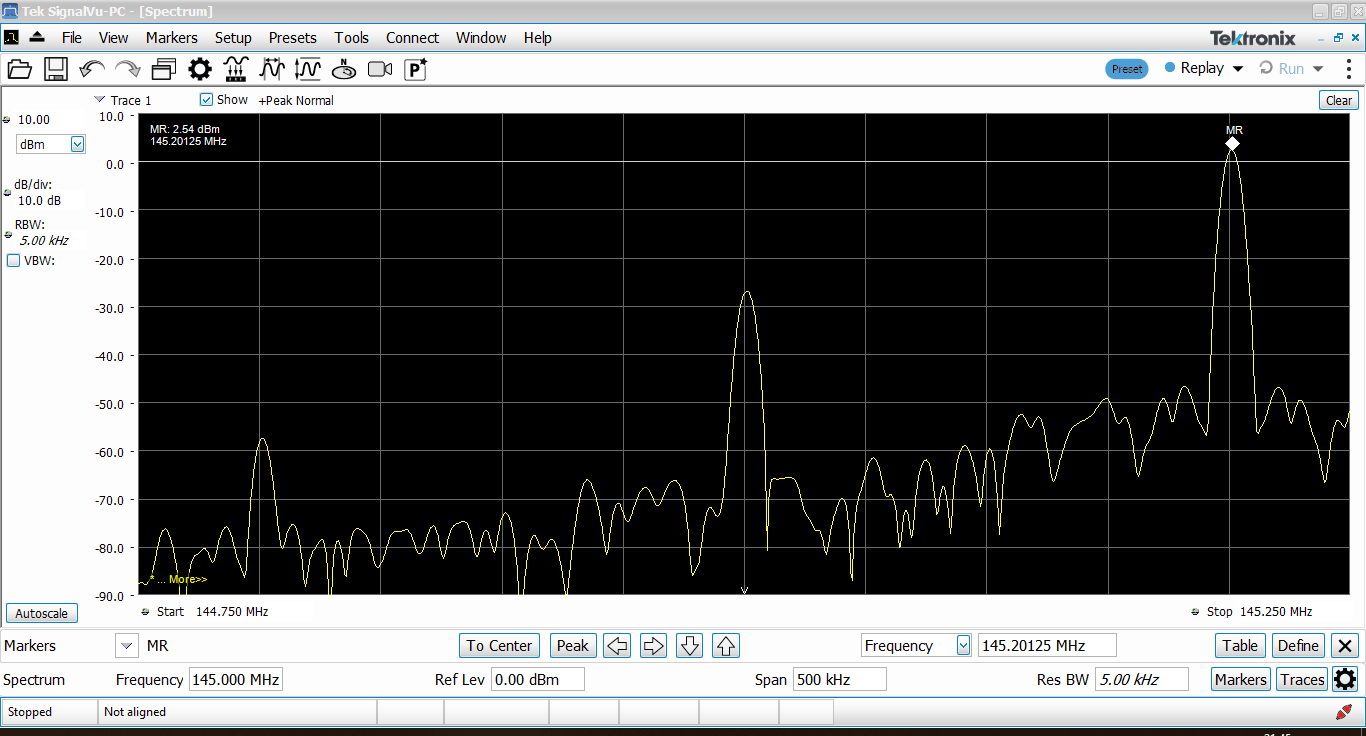
When you shift the frequency away from the center, you still see two peaks with lower amplitude. The one in the center is at 145MHz which is the carrier frequency. The smaller peak on the left is at 144.8MHz, lower side band of the mixing process. Although the LimeSDR uses IQ mixer for up and down conversion, the mixing process still results in image due to imperfections in the circuitry. Nevertheless, the main peak at 145.2MHz stands at +2dBm power level while the lower side band is 60dB down. The carrier still visible at the output of the spectrum analyzer is resultant of the frequency (base band + carrier) mixing process.
A higher gain in the LimeSuite TX block will result in a higher power level. As mentioned earlier, you can go all the way to 100dB gain level.
With this, we conclude this article. Let me know your thoughts in the comments. If you have questions, let me know below and I will make sure to come back to you.
Gr8 job Salil…..hope u guide us wid our queries of SDR
Hi Salil, first of all thanks a lot for your details explaining. I have a confusion on selecting the baseband frequency of signal source and selecting the frequency of Limesdr tx.suppose I want to transmit 2.4 GHz frequency in that case what will be my baseband frequency and analog filter bandwidth.will you please help me to understand this concept.🙏
You can set your TX frequency to something like 2.4GHz +/- baseband center frequency. Or you can always keep your baseband to 0. In that case your TX frequency will be 2.4GHz + 0 = 2.4GHz. Hope you get the point.