
Using the Signal Integrity tool in Altium Designer – Part 2
In part 1 of the article series, We learnt how to set up our design for performing signal integrity analysis using Altium’s in-built Signal Integrity tool. The process turned out to be quite simple and we ran the tool for our initial sanity checks. Once the sanity check passed, we were able to view the crosstalk and reflection waveforms and run an analysis on them. In this article, we will dive deeper into understanding the results the signal integrity tool offers us.
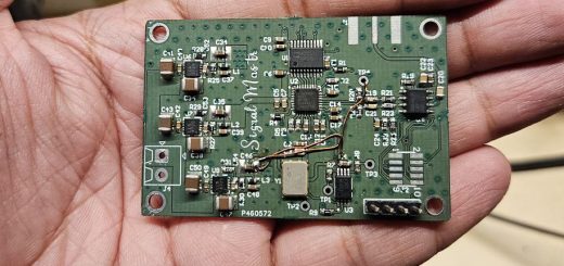
This design contains a Lattice Crosslink NX FPGA and an ISSI HyperRAM that’s clockable to run at 166MHz. Before we even start the simulation analysis, we must have at hand the expected response from the digital interface. For example, the rise-time, slew rate, crosstalk threshold, ringing, etc. Also, having specifications such as the channel’s loading capacitance would help obtain precise results.
We start with the part datasheets to understand the desired channel characteristics expected for the correct working of the device. The test conditions mentioned in the datasheet define the slew rate and loading capacitance of the connection.
- Loading capacitance: 20pF
- Slew rate (minimum): 2V/ns
The 20pF capacitance appears to be quite high and I am sure my design does not capacitively load the net that much. I will be treating the 20pF as the maximum. Additionally, the 2V/ns slew rate means that the voltage transitions from 0 to Vccq at a rate of 2V/ns. In my case, the Vccq is set at 1.8V. The slew rate defines the minimum required value, implying that we can go faster if we can. Now, we have two reference parameters to meet in our design.
Crosstalk, overshoot, undershoot, etc. are some parameters we need to observe in the simulation data. Overshoot and undershoot are the result of reflections. When a given signal goes back and forth along the PCB trace, it’s known as a reflection. Reflections also result in crosstalk distortion. As a result, the waveform gets spoilt, and we start facing signal integrity issues. Therefore, keeping reflections to a minimum results in a better-performing PCB with minimum crosstalk.
Analysis
Now, we have some parameters to start and we already have the Ibis model for our parts setup in Altium. Let’s run the simulations and observe the waveforms. Before we run the simulations, Altium would ensure your design meets all the set rules. Any rule violation would prevent the simulations from going forward.

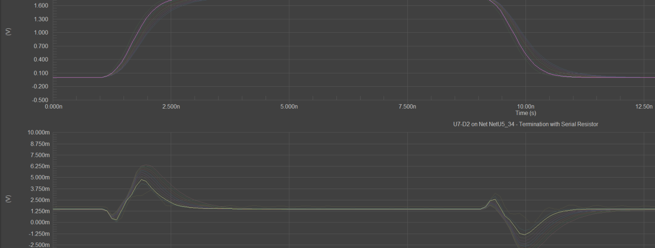
I have set the NetU5_33 as the aggressor where this net would carry the signal while NetU5_34 would remain silent. Any disturbance in form of voltage that we observe on NetU5_34 would be purely a result of signal flowing through NetU5_33. For the first case, we have no termination on the ends of both the traces. We observe an induced voltage of not more than 5mV on the victim line which is approximately 0.27% of the high voltage level.
We can also observe from the plots that the rise time is less than 1ns. By adding series termination resistors, the rise time increases proportionally. Altium’s Signal integrity tool allows us to experiment with a range of termination options without actually modifying the layout. While setting up the models, I also enabled “series termination” option to sweep through resistance values from 10 Ohms to 150 Ohms. Usually, a series termination in range of 10 ohms to 50 ohms is more than enough to make things better.
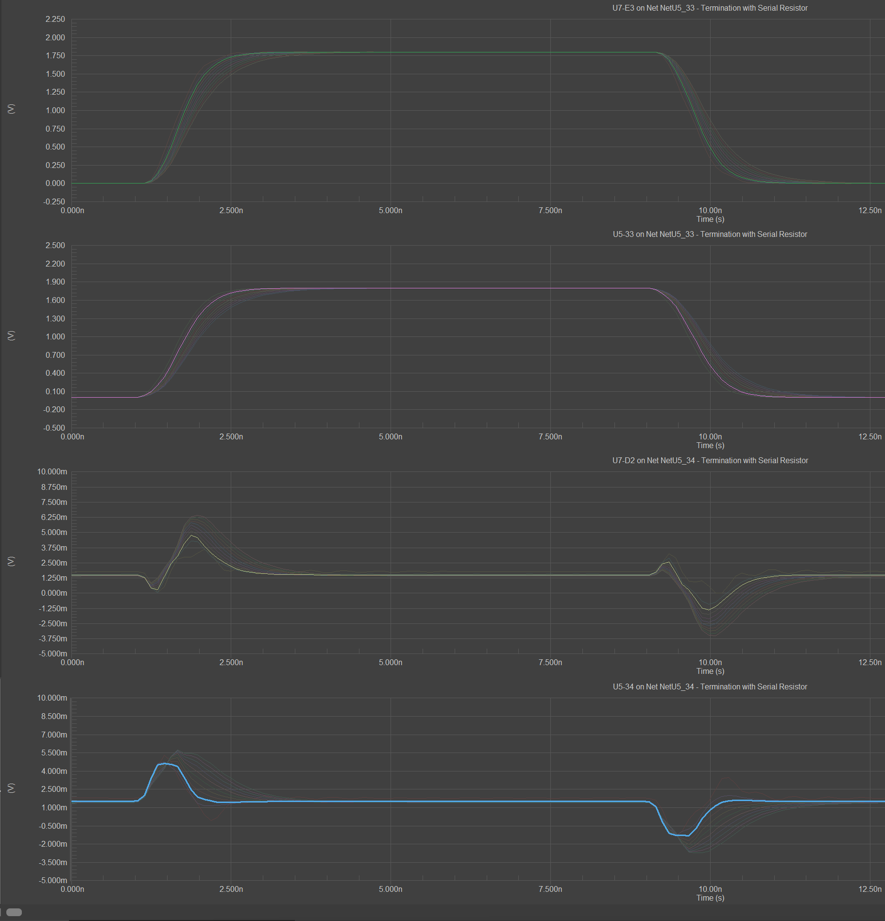
Reducing the rise time by some amount also improves the crosstalk performance as well as subsides the reflections.
Similarly, we can carry out simulations for the rest of the digital lines and find signal integrity issues.


Voice of the people