Android based wireless ECG monitoring (UPDATED)
From quite some time I had been busy trying to perfect my real time ECG monitoring system. I was able to look at my ECG after a tedious task of recording it via sound card and then processing it in MATLAB. If you have closely read my previous post, then you will know that I was having an analog front-end based on INA128 instrumentation amplifier and then I was sending it over to the microphone input of my PC. I recorded this signal at a sampling rate of 1000 Hz and then processed this audio file in MATLAB to get a signal which looked just like a real ECG.
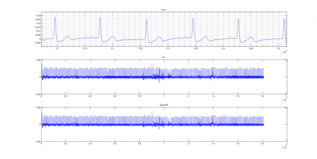 The first image on the top shows the zoomed section of the recording. From this image, it is absolutely clear, the PQRST points on the ECG graph. This being a 3-lead ECG, we can only see the heart from one perspective, but it is enough for preliminary diagnosis.
In order to reach to this stage, I have to do process the signal, filter it, smoothen it and then display it. Pretty long process if you are doing it all manually.
Bring in the automation
Automating the entire process was my goal back then. I wanted to eliminate the need of using a sound card to view my heart function. The device was barely portable because of two reasons. One, the circuit was poorly designed and therefore, there was a lot of motion artifact. I have to hold my breath in order to have a clean ECG. The circuit also did not have a good input impedance due to which the amplifier often saturated giving me a flat line!
Now the second reason is, I had to sit near my PC to record using the microphone input cable.
The goals
From this introduction, the goals should be pretty clear.
1. to have a portable system
2. To redesign the front end for obtaining good quality signal
3. To have multiple sensors (Still working on it)
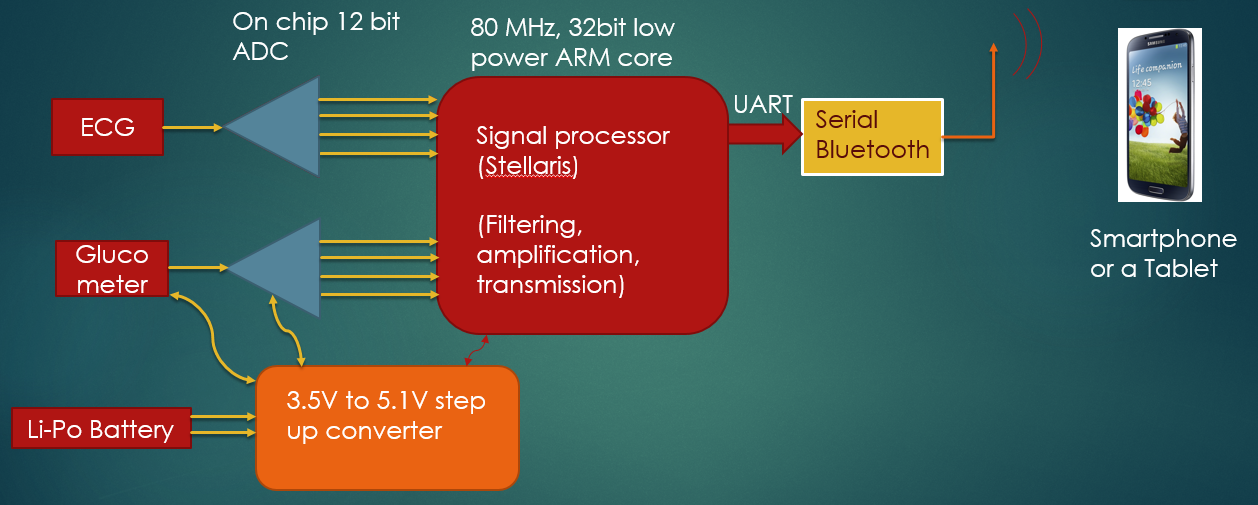
Over all system block diagram would look somewhat like this.
System plan
How I managed to automate the process
For any mildly experienced person, the answer is to incorporate a microcontroller in the system. By looking at the system plan, there is a microprocessor at the heart and all the analog front ends on the left and a wireless transceiver (Bluetooth) on the right.
At the very beginning I tried my luck with Arduino board. All I had to do is feed the analog signal into the ADC channel of Arduino and have the analog to digital conversion task be handled by the controller.
To have a portable system, you always need a PC for testing. It was all good while I was still using a PC to view my graphs. Processing was a quite handy tool to view the real time ECG signal coming from my heart.
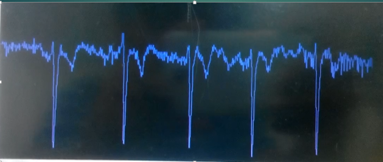
ECG on processing
I could have gone ahead and built an application to run on the PC, but that was not what I wanted. What I wanted was to be able to view this graph on an ANDROID PHONE!
But I was not confident to start working on that part unless and until I had a good quality ECG signal on the PC. If you do not have a proper working analog front end, then there was no point in proceeding further.
Designing a good ECG circuit
If you do no know about the basic building blocks of ECG circuit, then I suggest you to go back here and here to learn about it. We begin modifying the circuit shown in those previous posts.

ECG front end circuit
We start with the INA128 instrumentation amplifier on the left hand side. Look carefully those capacitors C10 and C9. For those who do not know much about PCB designing, here is the explanation. The power rails often pick up noise or inherently have some noise coming from the circuit. If we allow this noise to enter our circuit through the power rails, I dont have to explain what would happen. Since, the noise can be picked up over the rails, we try to place these decoupling capacitors as close to the device as possible. This decouples the noise and lets the device have clean DC power. It is important because we want a clean ECG signal over which we do not want to do much signal processing. Any noise in the circuit will show up at the final output.
Opamps U1A and U1D form the band pass filter circuit. Again look closely at the numbering. I have used U1A and U1D, I could have used U1A and U1B, but that could have changed my PCB layout. You can choose any opamp in the IC which makes your life easier while routing the board. (I have indeed used the opamps U1B and U1C further down the circuit and not have let them go waste)
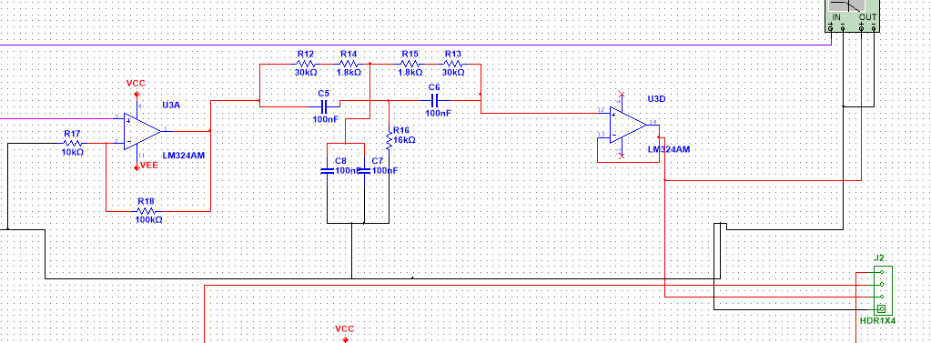
Opamp U3A is an amplifier with gain of 10. I have made this amplifier drive the notch filter which is ahead of it.
ECG notch filter
The notch filter is an optional components. INA128 works pretty well at cancelling the common mode noise at the input. But in my case it still had some 50Hz power line noise. In my past versions of the circuit, I had the amplifier U3A at the very end of the circuit, but that did not seem to work. The notch filter was overloading the band pass filter causing the voltage to drop to zero and hence my decision to keep this amplifier right before notch filter so that this amplifier would rather drive the notch. Opamp U3D working as a buffer again to prevent any kind of overloading.
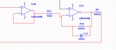
The circuit does not end here. We also need the right leg drive which is quite useful in improving the SNR.
right leg drive
Please note that the black lines represent ground. And now its time for the full circuit.

ECG circuit wireless
Now that we have a nicely working ECG circuit we are ready to move one step ahead.
Implementation on the PCB
Please note that this circuit is available for sale. Contact me at salil2106@gmail.com for the circuit.
The microcontroller and Bluetooth interfacing
Like I said, I had been using Arduino at the beginning. Problem began to arise when I interfaced the HC-06 bluetooth module with it. It was quite annoying to program Arduino while the bluetooth was connected to it because it uses the same Rx, Tx ports as the one that are connected to USB chip. I could have used the Software Serial functionality. But considering the future expansion of my project, I thought that it was time to let go of Arduino and starting hunting for a new candidate.
I found Stellaris Launchpad, 32 bit, 80MHz, nuff said! It had just too many Serial ports, SPI ports, internal RTC, dedicated features for DSP and the list goes on.
Now anyone with some experience in microcontrollers would say that having a new controller is tedious, because you have to port your software over to the new one. New controller would have a different architecture and other differences. There was Energia IDE which allowed me to port my Arduino code over to Stellaris with minimal modifications!!!
I would highly suggest you looking into Energia IDE. It has coding similar to that of Arduino and you also have the pleasure of incorporating functions from Stellaris API (which are just too powerful). All of this just for $12.99! There was a discount going on back in August and which is why I bought it for $7.99 😛
I was quickly able to interface the bluetooth module. I took help of the Amarino MeetAndroid library which enables easy interfacing and does all the hard stuff for you. The biggest program came when the voltage levels mismatched!
Power problem
Stellaris can only accept power through the USB. If you try to bypass the voltage supervisor, it just shuts down. There, an obstacle in the path of portability! Not to worry, there was an additional USB host port on Stellaris through which I was able to give power using a battery.
Our Li-ion batteries only give out upto 3.8 V and USB works at 5V. Also, our ECG circuit requires nearly 5V to operate properly. Now how do I give power to these devices?
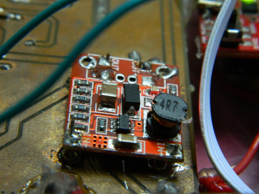
Answer was simple. A step up boost converter did the job for me. It boosted the voltage from a minimum of 2.2 V up to 5.1V. Enough for powering up the entire system. You can check out the boost converter from ICStation.com. Not to forget that we also have a bluetooth module sitting in our system which also needs power.
The Android application
Android is where we want to display our ECg signal, temperature sensor and the glucometer (which I still have not talked about).
Amarino library provides a pretty functional app called SensorGraph which takes serial data from the bluetooth and plots a graph on the phone. It worked pretty well, but viewing the graph was not all I wanted to do!
If you know Android programming, you can easily work around and add in some interesting features to that app. I am a newb, and I took quite a while to learn it.
Having a medical device monitoring yourself, why not let others view it as well? I decided that this app must upload this data to the internet and have others open a website to view it. Perhaps even a doctor could login and view the ECG and other medical records of you. May be if the doctor sees something wrong he can alert me? (Just in case he happens to open my records)
This is how our android application is looking so far.
Going online
When it comes to storing records, the first thing that came to my mind was to use MySQL database. It is quite easy to use and serves the purpose quite well.
Android does not have an API for directly accessing the MySQL database (WHAT?!)
So, we have to “POST” our ECG values on to a PHP page and the PHP page would store the data onto the database. Sounds simple, but its not (atleast for a newb like me).
By POST, I actually mean POST. Here goes a code snippet.
|
1 2 3 4 |
$patient_name = $_POST['patient_name']; $gluco = $_POST['gluco']; $temp = $_POST['temperature']; $ECG = $_POST['ECG']; |
On the Android side, we first need to take the data, which is in string format and then form a Basic Name Value pair which is basically the name of the field and the corresponding value that we are going to “POST”.
|
1 |
nameValuePairs.add(new BasicNameValuePair("gluco", dataToBePosted)); |
Now, we need to “POST” it…
|
1 2 |
httppost.setEntity(new UrlEncodedFormEntity(nameValuePairs)); HttpResponse response = httpclient.execute(httppost); |
Once we get a proper response from the web server, we continue graphing.
The android application works excellent even with EDGE / GPRS connectivity. This proves that our device can also work in remote rural areas with poor internet quality.
What have we done until now
1. We have the ECG, we feed it to the ADC of the microcontroller.
2. We send it over bluetooth using MeetAndroid library.
3. On the android application -> We are plotting the graph continuously. When a user enters his name and presses “Record and upload”, 1500 samples of data are recorded and uploaded to the server as shown above. In short, we have an Android based wireless ECG monitoring system so far.
4. Store the POSTED data onto the MySQL server.
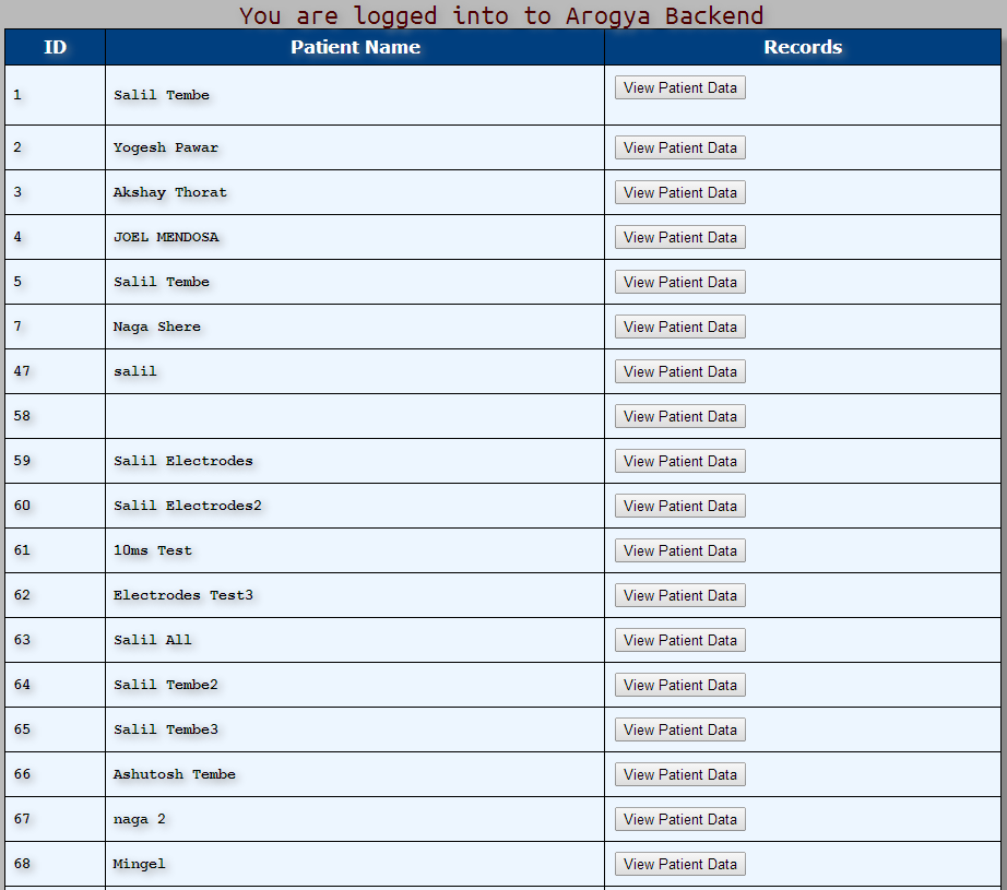
5. When a user accesses the webpage “patients.php” he can look at all the records.
This is how the “patients.php” looks like.
Patient Database
Most of the entries are mine which were stored in the process of testing. But you get the point!
And now let us have a look at how the ECG looks online!
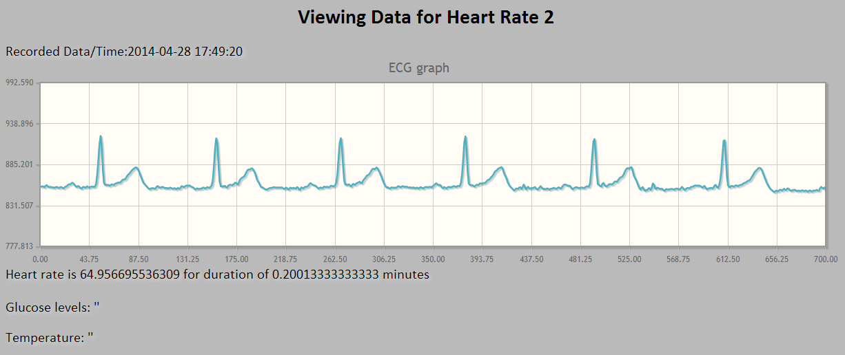
ECG signal uploaded online from the Android app
If you look closely, you would be able to see that the PHP script also calculates the Heart rate of the given ECG signal. We have tested it and it is pretty darn accurate.
Some technical details
The battery operated device works for 2 to 3 hours on a single charge. We are planning to use Bluetooth Low energy in future revisions so that the battery life elongates even more. Additionally, if we replace LM324 Opamps with OPA333, we can achieve significant power cutting.
We are also working with turtle’s pace on pulse oximeter and blood pressure.
Our final goal is to put this all on a single circuit board and have a seamless working medical device.
We are accepting all the possible help you can provide to us, including help in development and financial support.
This is how our prototype looks right now.
UPDATE
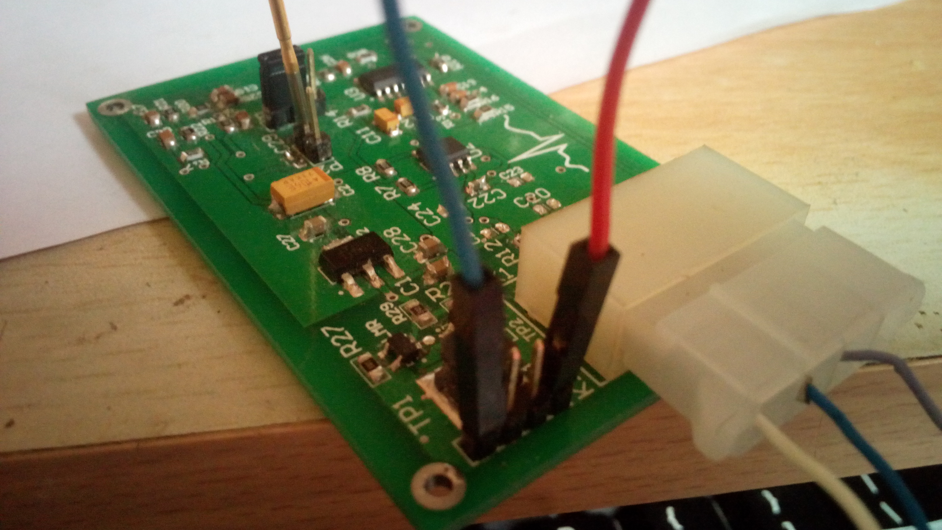
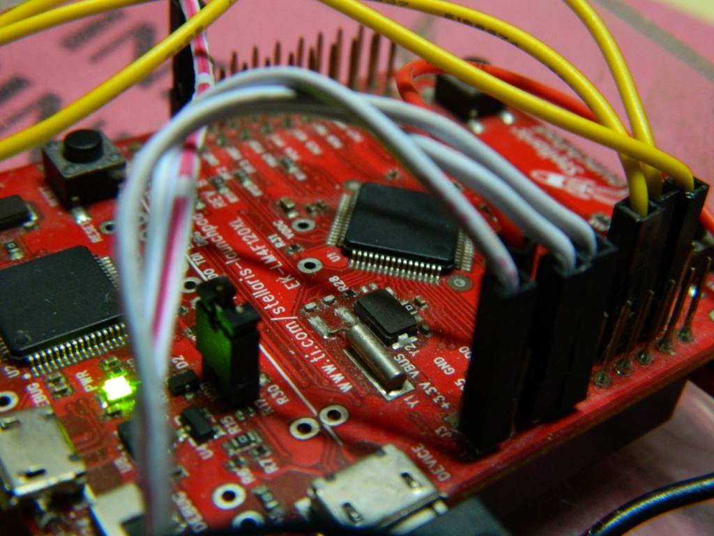
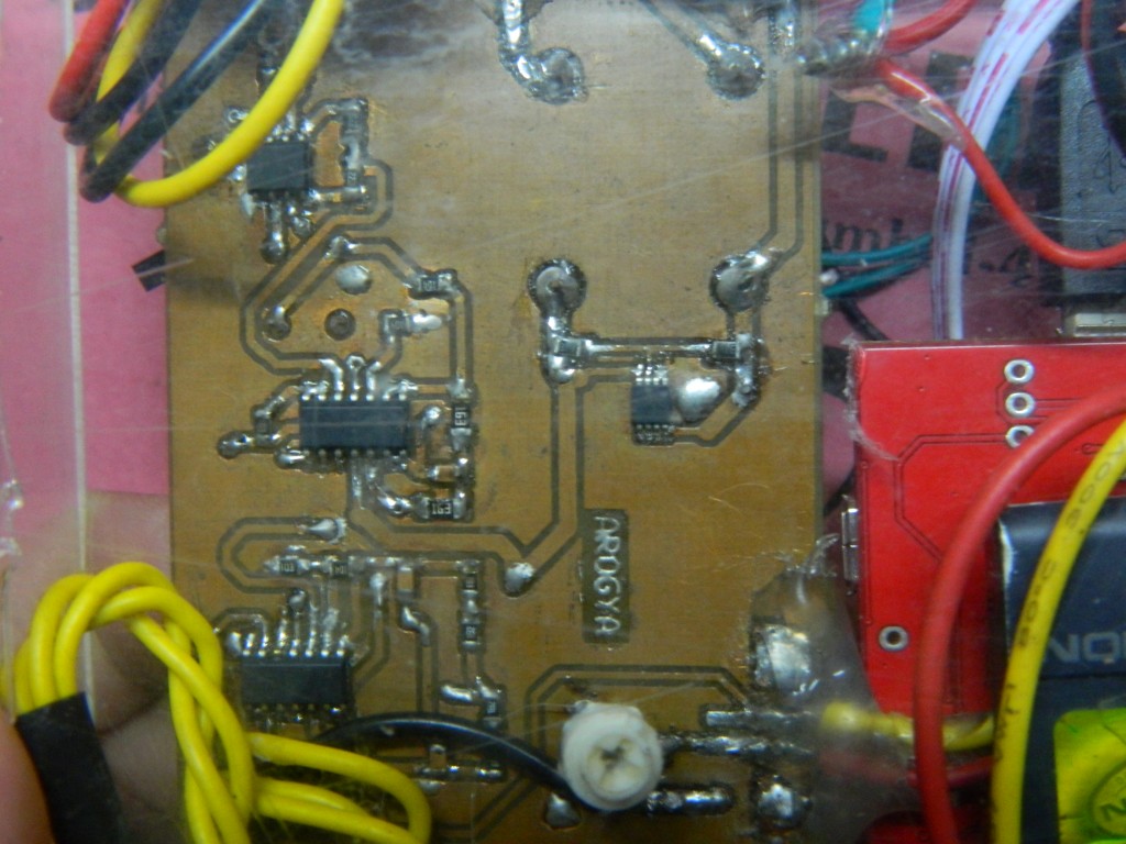
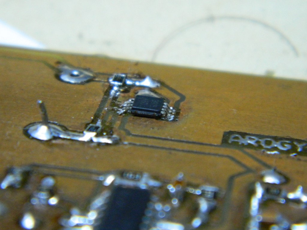
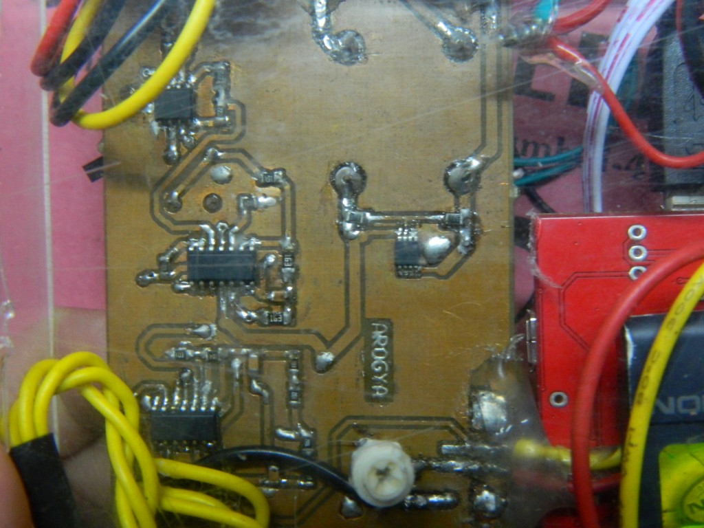
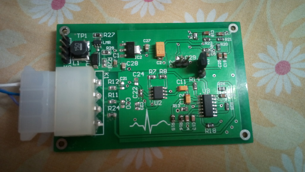
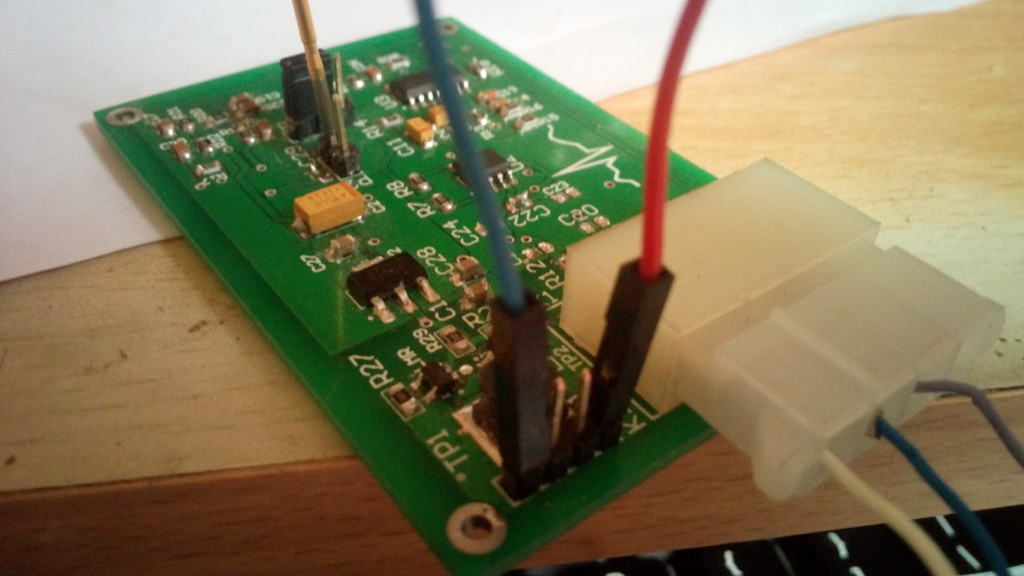
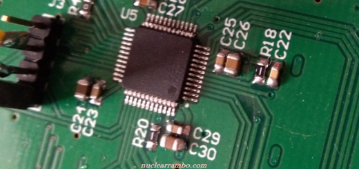
I just created a ECG front end that works great with all the microcontroller ADCs. Here are some pics. Nothing great, I simply got it fabricated by professional services.
SPONSOR MESSAGE
Seeed Fusion PCB Assembly Service offers one-stop prototyping for PCB manufacture, PCB assembly and as a result they produce superior quality PCBs and Fast Turnkey PCBA from 7 working days. When you prototype with Seeed Fusion, they can definitely provide Free DFA and Free functional tests for you! Check out their website to know about their manufacturing capabilities and service


Hi
I saw previously you offered the fully assembled boards of your ECG circuit for sale – would it be possible to buy this new board? I have the Stellaris Launchpad and would very much like to try this project.
Thank you very much in advance,
Mac Ha
I would definitely make a new one for you and send it on your way. I have emailed you.
Hi nuclearrambo,
I’m trying to implement an informatic system (a mobile app and a web app) for a school project to upload gucose data taken from a sensor within 3 months. It’s something like your system, however my project is more oriented to the data analysis algorithms, cloud storage and appropiate mobile network management. Not everything is done but I’m in the phase where I need real data to make some tests.
I have thought in 2 ways to approach this: one is to take data from a commercial glucometer like the bayer or the j&j ones, adapting the usb or rs 232 outputs to interface it to a microcontroller like arduino or pic or st, etc. And follow their communication protocols to get the glucose data. The other one is to make aquisition by myself to acquire analogic data and send it on my way.
Which approach do you recommend me to take? Do you think I could finish it within 2 months or so if I make the acquiring module? Where could I get the sensor?
I consider that the development of the sensor module is out of the boundaries for my project and that’s why I dare to ask if it is possible to acquire this board but with the glucose sensor to inmediately test shipped to Mexico. If it is possible to buy one how do I proceed to?
Well I hope they weren’t many questions and I appreciate your time for reading this.
Best Regards,
Felix
I would suggest go with the commercial glucometers. Making these by yourself would result in extremely inaccurate data.
As for acquiring my board, I do not have any spare boards at the moment and due to busy schedule I doubt I could make one and send it on your way. I could send you the schematic and art work and you can have a look at it.
buen dia. seria posible que me colaboraras con el codigo en energia ya que no he podido conectar el tiva c lounchpad con el modulo bluetooth
Hi Nuclearrambo,
Nice work!!! Currently myself working on portable ECG device which communicate to android device. i have read the data from device. now i got struck with the ecg signal processing.could u suggest me the better algorithm for processing. if you send ur android source code will be helpful. my email id nmarijoe@outlook.com. Thanks in advance
I am not doing any kind of signal processing on Android. Although I am detecting R peaks on the microcontroller and also measuring heart rate on the cloud after data has been uploaded.
thank u for this interesting tutorial
although , im having problems identifying the components through this low quality schematics
can you plz send me part list , or another HQ schematic with clear components values
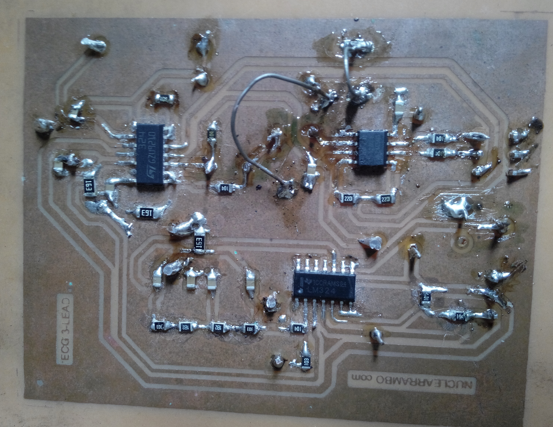
in the schematic i can see 2.2k res. connected to pin 1 of the ins. amplifier , but in the real PCB i see 223 smd and 220 connected to pin 8 ?!! am i wrong ?
my sec. question : would it differ if i used ad620 instead of ina128 ?
thanks alot .
Hello,
I am developing a similar Android application for my thesis, but with the communication by USB instead of bluetooth. I found a problem to recognize the format in what the bits are sent by the ECG sensor. What sensor have you used? Did you have problems to interpret the bytes of data by bluetooth? What was the format?
Thank you.
The bytes are read from the ADC register of the microcontroller. They are unsigned 16 bit integer format depending on the ADC used. I dont think it should be that difficult.
Awesome circuit.
Got the circuit in just 4 days.
Thanks for the guide and keep up the good work (y)
Thats great. I hope you are enjoying your PQRST 😀
Good one want to buy it
I have sent you an email.
rohankolekar95@yahoo.com
hi. i would like to know about the electrode, which is used for this circuit. is it non-contact type or dry-contact type or gel electrode? if it is not a non- contact type electrode how can improve this to measure the ECG signal non-contact manner.
Would like to buy it.
I am looking for ECG interface circuit for android. Hope to use it for measuring heart rate variance (HRV).
Can your circuit working with HRV calculation apps? In another word, can your bluetooth connect with android apps.