
Homemade sound card ECG circuit
SCROLL BELOW TO SEE LATEST UPDATES
4.4 The Basic ECG Circuit We started to build the first ECG prototype circuit after doing a lot of research and studying about the requirements of the ECG system. We wanted the ECG circuit to be as simple as possible and yet give us the desired output required for primary diagnosis of heart. The simplest circuit ever possible to detect ECG is built with a single operational amplifier. The operational amplifier circuit is shown below:
 |
| From May 6, 2011 |
<!–[if !vml]–> <!–[endif]–>How it works? The ECG signal is picked up by the positive terminal of the op-amp. The negative terminal and the output have a feedback resistor of 100kΩ. The gain is set to 100 with this resistor. A capacitor of value 0.1µF is connected across the two input pins. Since the capacitive reactance goes on reducing at high frequencies, the capacitor helps in reducing the HF noise. High frequency noise/interference is bypassed using this capacitor. This works because of the law of capacitive reactance: Xc = ½πfC The most persistent of all noise frequencies is the 50Hz power line noise. The output from this circuit was observed on a PC based oscilloscope. First the output was given into the sound card microphone input. The signal was recorded using software called Gold wave®. This software is specially designed for sound and audio editing. Since the ECG signal lies in range of 0.5Hz to 35Hz, this tool was able to record ECG signal. This software also had inbuilt digital filtering and noise reduction options. Using this we were able to remove the persistent noise and obtain a recognizable ECG.
 |
| From May 6, 2011 |
 |
| From May 6, 2011 |
 |
| From May 6, 2011 |
 |
| From May 6, 2011 |
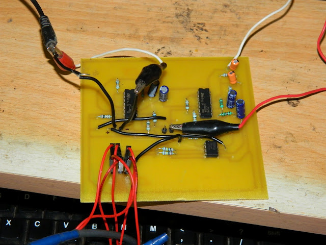
4.5 The 3 Lead ECG circuit The simplest ECG circuit was not able to remove the prominent noise signal and it was not able to give us a clean ECG signal which could be used for primary monitoring. The reasons for this are that the circuit lacks in filters. Filters are necessary to remove the unwanted frequencies apart from the frequencies lying in the 0.5Hz to 35Hz band. Secondly, the circuit had a single operational amplifier which didn’t have a very high CMRR. This resulted in low rejection of common noise signal on both the input pins. Most of the ECG signal was lost because there was no proper filtering. In short, noise created a lot of trouble and a lot of work had to be done to remove this persistent noise. The solution used is a differential amplifier that is based on a classic design. This ECG has 2-leads and a RL-drive. The RL-drive works as common ground for the circuit and it also inverts unwanted noise that is picked up by the leads and sends it back in to the patient. The differential circuit is an INA128 which has two inputs where the two signals comes in to the circuit and the difference between these two signals is amplified 20 times. The INA128 IC is an instrumentation amplifier with a CMRR of 107dB, which means a pretty good rejection of signals which are common to both input pins. INA128 will effectively cancel out the common signals. Another advantage is the low DC offset voltage and very little drift current, both of which are very important in obtaining a good quality ECG signal. The first stage has to be perfect to get the later stages help in obtaining proper signal. The circuit works by providing 2 input leads which are connected to the right arm and left arm and the 3rd lead is connected to the right leg. Heart generated electrical pulses which causes the heart to beat. These electrical pulses are picked up by the electrodes and given to the input terminals of the instrumentation amplifier as shown above. The cables used in the path from skin to amplifier are shielded coaxial cables. The shield proves to be very useful in ECG system because it capture most of the noise which could possibly induced over the signal-carrying cable, which in turn destroys the quality of the ECG signal. The shield is then grounded to completely drain the induced voltages, thus preventing the noise to corrupt our ECG flowing through the coax. The INA128 is set to provided gain of 26V/V by the industry standard equation of 1+50k/Rg.
|
FEATURES of INA128P
|
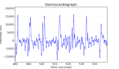
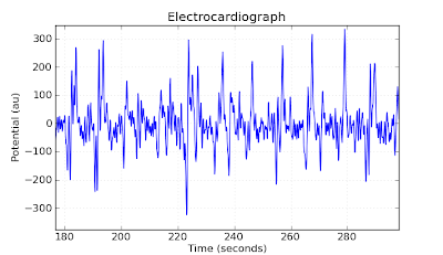
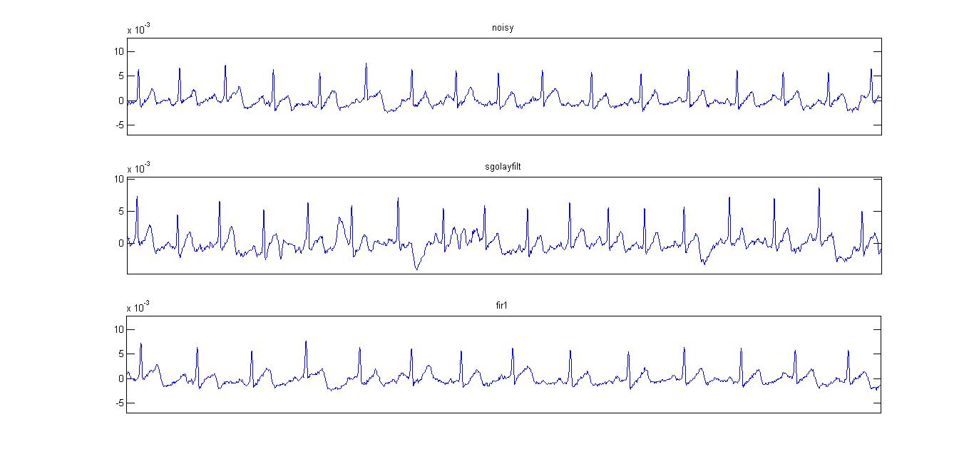
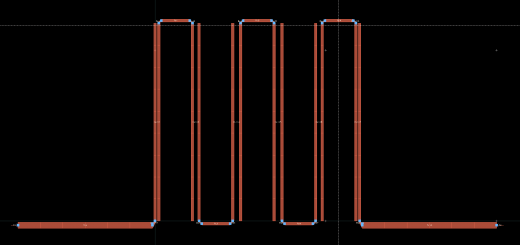
We had selected the gain to be much less, because it is the first stage and it has to deal with heavy amount of noise voltages. If we had kept a higher voltage in the first stage itself, the amplifier would amplify the noise along with the desired signal. Amplifying such a large amount of persistent noise would instantly saturate the amplifier preventing any signal to flow through. The voltage acquired at the two input leads i.e. RA and LA is then inverted using the buffer amplifier and the inverting buffer amplifier and then injected back into the body to cancel the existing noise on the body. In this way the noise level is suppressed at a greater magnitude and helps a lot in acquiring a good signal. A further stage in this is to use band pass filter. The reason for using band pass filter is to avoid the DC voltages created by the muscles and to avoid the high frequency component which is not of any use to us. The high pass filter section has a cut off of 0.5Hz and the low pass filter has cut off of 35Hz approximately. Since the low pass cut off is must lower than 50Hz, it helps in suppressing some of the 50Hz noise as well, which is a good thing. We preferred passive filter topology i.e. using only capacitor and resistors to filter out the signal. Passive filters of 2nd order are implemented and they require around 10 seconds of settling time. That means you need 10 seconds for the circuit to settle down and start showing you correct signal. Active filters if at all used would yield better result and the settling time for them is less than a second. The above figure shows the filter schematic with values calculated using the equation: F = 1 / (2*pi*RC) This stage receives the signal from the first stage i.e. INA128. After this stage comes the final amplification stage in which the filtered ECG signal is amplified using non-inverting operational amplifier with a gain of 100 to 220. This stage is necessary to bring the ECG signal’s peak-to-peak amplitude to around 2V approximately. Bringing the voltage level to 1-2V will yield a better resolution when given to the ADC of the microcontroller in later stage. A low amplitude signal given to ADC would require high resolution (>12bits) to be recognizable which would increase the cost and components. To avoid adding another ADC IC, we preferred to amplify the voltage level of the signal. The stage successive to this is where we will give the final ECG signal from the circuit to the analog-digital converter of the microcontroller. We will discuss about the microcontroller later in this book. Once the data is digitized, we can transmit this information to the computer where we can digitally filter the signal and plot it in real-time, or do whatever we want with it. The output of the final stage can be observed in the sequence of images below: Digitally filtered ECG.
 |
| From May 6, 2011 |
 |
| From May 6, 2011 |
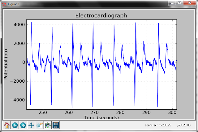
One a side note we would like to state that if you are going to work on a ECG circuit ever in your life, then you should first design the circuit on paper, test it on bread board by giving input from signal generator, but do not test the circuit by directly connecting to human subject. All you will get is severe noise which is very hard to get rid of. Once your circuit is working on signal generator input, immediately design a prototype PCB and then you may test the circuit on real human subject. According to our experience, the quantity of noise that you get from the breadboard circuit is so intense that even an 11th order filter could not remove the noise. On top of that, a series of high order digital filters were also used just to realize that it’s of no use unless we have a stable printed circuit board. Breadboard picks up large quantities of noise along it’s rails and so it is difficult to remove the noise. As soon as we had a printed circuit board the quantity of noise dropped drastically and we have a VERY VERY CLEAN ECG signal! In the above image you can clearly see the PQRST waves though they are inverted. This was recorded using the sound card input and audio recording software.
To find OUT ABOUT THE CIRCUIT please FOLLOW THIS LINK
REQUEST TO VIEWERS:
Send me an email if you want the matlab code for filtering.
UPDATE – UPDATE – UPDATE
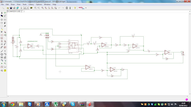
Also I am selling this sound card ECG circuit at a very cheap price. The circuit diagram for the sound card ECG is right below ->
The circuit diagram is now updated with much better filtering technique. A ready made PCB can be sent to you upon recieving you request for it. Please send me an email at salil2106@gmail.com if you need to buy the circuit at a low cost.
 |
| From ecg_dubai_guide |
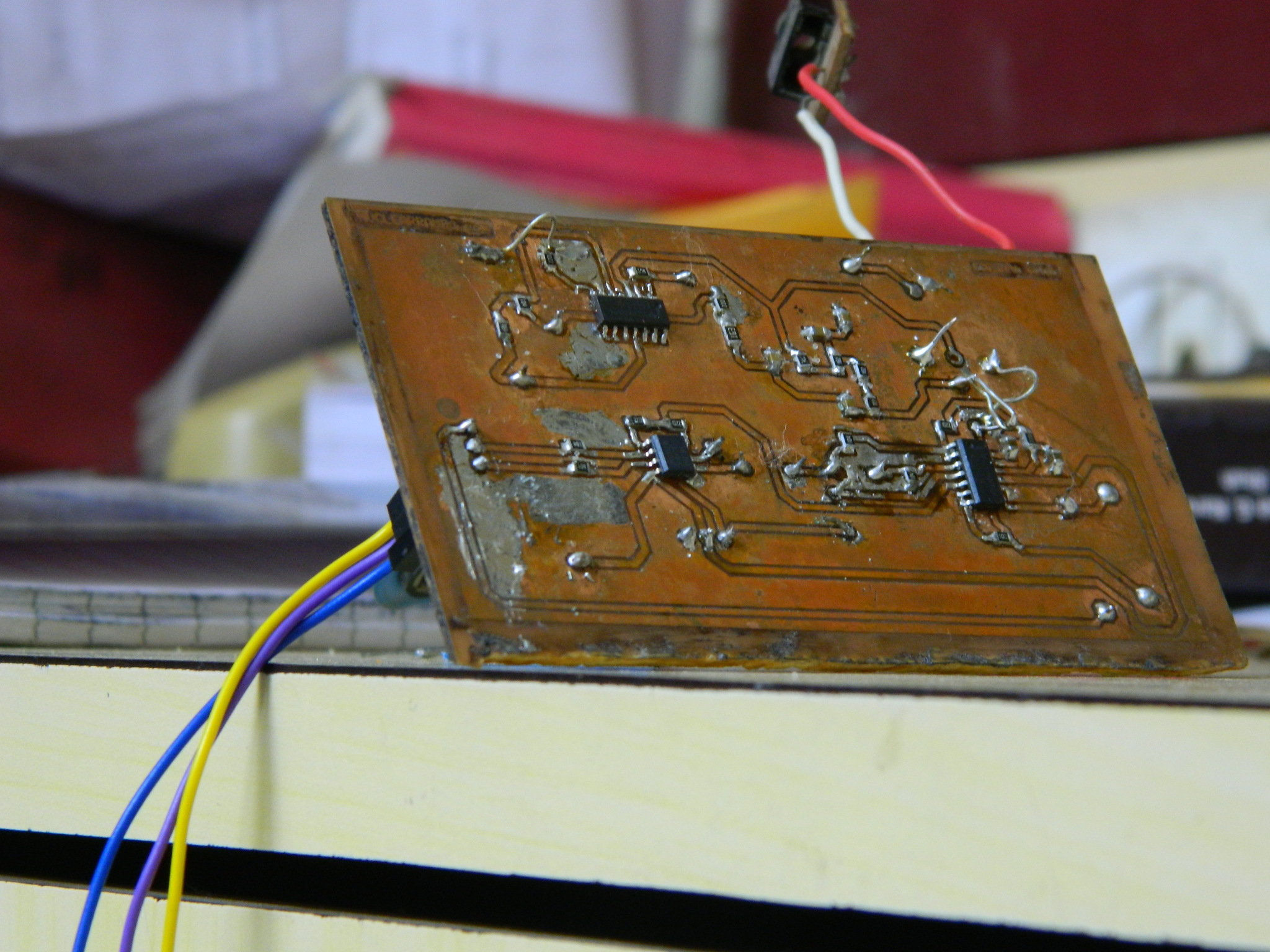
A new version of the circuit has been constructed and has a huge load of improvements. the biggest change is that all components used are SMD. Addition of ground plane and notch filter are a huge addition which helped remove the noise by a huge margin.
 |
| From Drop Box |
For a sharper image of the circuit diagram, please email me at salil2106@gmail.com or leave a comment.

UPDATE
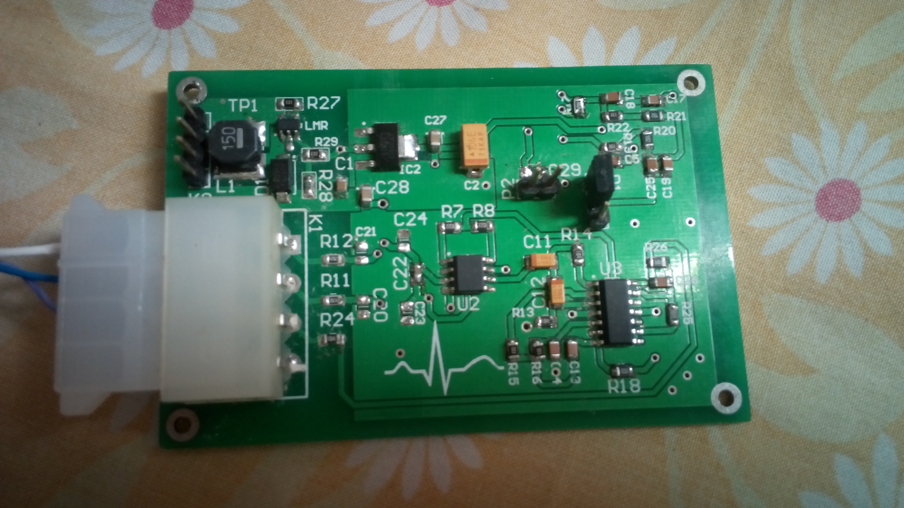
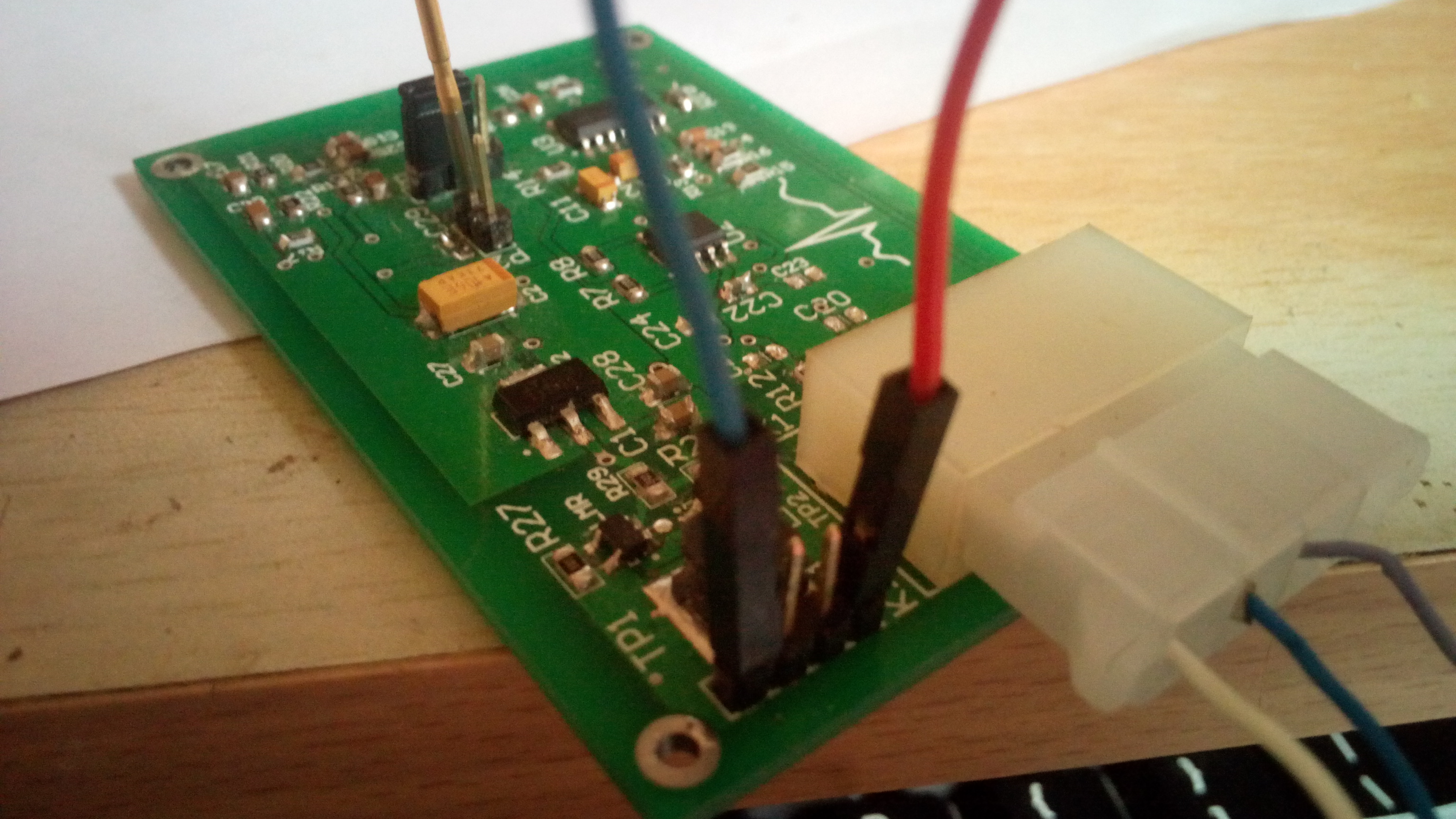
I just created a ECG front end that works great with all the microcontroller ADCs. Here are some pics. Nothing great, I simply got it fabricated by professional services.
BUYING instructions
You can buy the circuit for $85 + shipping. All you have to do is leave a comment below with your email address and I will contact you.
I am selling the ECG circuit board completely ready for your use. All the components will be soldered on the board.
NOTE: Building your first ECG will get you confused about a lot of things. It is not easy to identify ECG waveform when you are doing it for the first time. A small reference book is highly recommended for you.

This book has a lot of great information and I found it really very useful in my project.
And there is this reference book which helps in analyzing the ECG waveforms. This book describes various symptoms that could be diagnosed after studying the ECG waveform. This book has made ECG diagnosis much simpler for those not having medical background.


hola.
me gustaria saber cual es el costo de la placa y tambien cuanto me costaria el otro proyrcto ecg pero q esta trabajado con android
I dont know what you say man.. English please.
hi, is the circuit still up for sale?
Yes, we have made a better version of the circuit which is undergoing testing. We will update the post once it is fully ready in next few days.
hi, in my case i need to get the ECG signal through the cloth. is it possible to do using this circuit. And please inform about the electrode you have been used in this project. is it wet electrode?
The electrodes need to be direct contact with the skin. I have used AgCl one time use electrodes.
hello,
does this circuit come with a screen to get visual reading
Yes, on android. You may look at other linked posts.
Hello. Can I please get the diagram to analyze it? Thnx
hello sir, we are doing project regarding ECG , and we have to display it on MATLAB and for this we suppose to use goldwave software for converting ecg signal into matlab compatible file. so we request you to help us in this matter. plz kindly reply to this message.