Why ‘PPM’ matters in the GHz bands!
No matter what frequency you work on, a term called “ppm” always follows. Whether you deal with the good old HF band or you work at the Gigahertz band, “ppm” defines how accurate your frequency would be. Simply speaking, PPM stands for Parts per million. When it comes to frequency, it defines the maximum possible variation in frequency for every 1 million cycles (per 1MHz). Think of the resistor tolerance band. It gives us an idea of how accurate the value of resistance is going to be. A 1% tolerance on 10k resistor means that the resistor may have a resistance between 9900 and 10100. On the other hand, a 100k resistor with 1% tolerance will naturally give a larger resistance variation. Similarly, the term “ppm” defines a tolerance for oscillators and usually its best understood when you visually see the effect. That is exactly what this article will show you. Before we begin, lets go through a little bit of math.
How stable is your oscillator?
When you happen to work with radio receivers or transmitters, you will often find the oscillator stability in terms of “ppm”. For example, the Connor Winfield CWX823 25MHz TCXO has a frequency tolerance of 25ppm. Now, 25 parts per million can be represented mathematically as follows:
\(Tolerance = \frac{25}{1\times10^6}\)
Simply multiply the tolerance with the given oscillator frequency.
\(Frequency deviation = \frac{25}{1\times10^6} (25\times10^6 Hz)\)
\(= 625Hz\)
The number 625 Hz becomes your maximum frequency variation in both directions. Meaning, your 25MHz oscillator may at the most attain 625Hz higher or lower than the rated frequency. It’s represented mathematically as follows:
\(Frequency = 25MHz \pm 625Hz\)
You can easily do this calculation on a ppm calculator at jitterlabs.
What about PLLs?
All this while, we spoke about a single 25MHz TCXO and we learnt how to calculate the frequency variation due to tolerance. What if this TCXO works as a reference oscillator for your frequency multiplying PLL? It’s common to have TCXOs as frequency references for PLLs and these TCXOs commonly range from as low as 1MHz to as high as 200MHz.
PLL chips such as the very common ADF4350 or MAX2870 are capable of generating frequencies as high as 4GHz. The MAX2870 PLL can go all the way up to 6GHz. By the way, you can buy these PLLs on the cheap over at Amazon! What would be the implication of frequency tolerance at such high frequencies? The math is very simple! The frequency output of your PLL is as accurate as your reference frequency. If you use the same CWX823 TCXO with 25 ppm tolerance, 6GHz generated by your PLL would also have the same tolerance or slightly worse.
Lets run our frequency through the above equation and see where we land at.
\(Frequency deviation = \frac{25}{1\times10^6} (6\times10^9 Hz) \)
\( = 150kHz\)
A whopping \(150kHz\)! Again, we must note that this large variation depends on various conditions. The three most common variables deciding this stability are the environmental temperature, supply voltage stability and load impedance. Additionally, a fourth parameter may also play a role which happens to be mechanical stability. If your circuit happens to vibrate a lot, you will see its effect on the reference frequency. Usually, mechanical vibrations spoil the phase noise to some extent and may also produce weak amplitude modulation.
A small demonstration
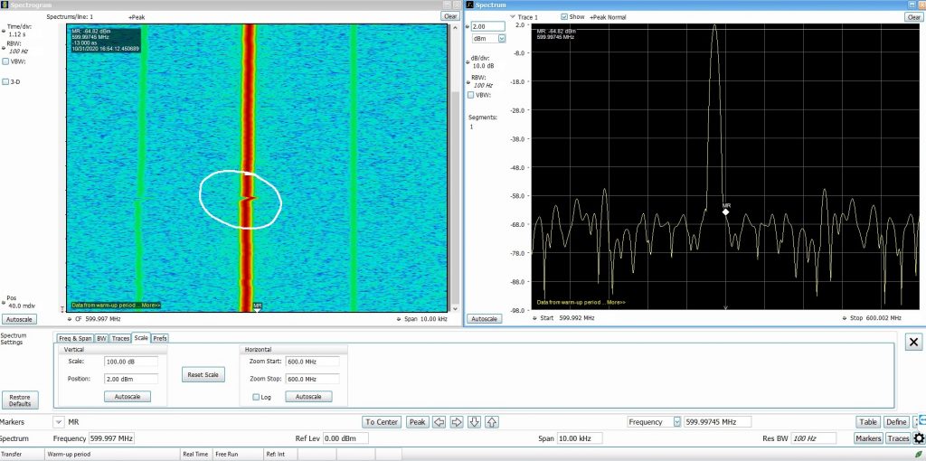
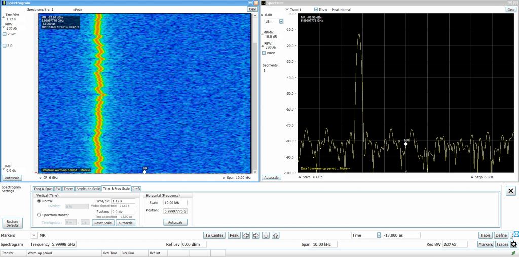
In both the images, the spectrum analyzer settings were kept fixed. The RBW was at 100Hz and the span at 10kHz. Looking at the first image (600MHz), you can see a small shift in the frequency marked in a white circle. That is when I blew cold air over the TCXO resulting in instantaneous frequency drift. If you are wondering, I am using a RSA306B spectrum analyzer from Tektronix.
In the second image, I generated a 6GHz tone with the same MAX2870 PLL. The frequency variations now become very visible. Imagine having a Ku band LNB with such poor reference oscillator. The frequency stability is quite poor and that’s one of the reasons why having a carrier tracking demodulator on the receiving end becomes mandatory. Those operating on the QO-100 would know the implications of having such poor reference oscillator. While transmitting, there’s a chance that your TCXO’s poor stability will create interference across the communication channel. While receiving, it becomes impossible to demodulate SSB signals because everything is drifting up.
There are however, software tools that lock on to a CW beacon which helps in correcting the receiving LNB’s frequency drift.
Oven controlled crystal oscillators for better PPM
The higher you go in frequency, it becomes absolutely important to have a very stable reference oscillator. Some oscillators with temperature control (OCXO) have a tolerance as low as 30ppb! For example, have a look at the OX204 from Vectron that comes with 30ppb (parts per billion) tolerance aging per year. Now, had I generated 6GHz with this 30ppb oscillator, the maximum frequency drift would have been only \(\pm180Hz\) and that’s a worse case scenario. Typically, it would be much lower.
Such frequency stable OCXO’s often find use in radar systems where pulse to pulse phase stability becomes extremely important for achieving good range resolution. When it comes to frequencies that are in the range of tens of GigaHertz, such precise oscillators are the only things that make the day simpler. Several kilohertz of drift at 30GHz, easily propagates down into the baseband resulting in a signals that requiring tremendous signal processing to do necessary corrections.
Anyway, you got the idea. A stable reference can easily save you any day.

Well described, explained thoroughly.